Question
Question: Write Kirchhoff’s first rule (law of junction). Drawing a circuit diagram of Wheatstone bridge, deri...
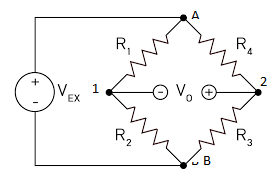
Write Kirchhoff’s first rule (law of junction). Drawing a circuit diagram of Wheatstone bridge, derive condition for zero deflection in the bridge.
Solution
Hint: Kirchhoff’s first rule (law of junction) is completely based on the law of conservation of charge. Deflection in bridge is calculated by a Galvanometer, it shows zero reading when there is no voltage between the ends. Hence the voltage Vo would be zero.
Useful formula:
Ohm’s law is given by,
V=IR
Where, V is the voltage between the resistors, I is the current through the resistor and R is the resistance of the resistor.
Complete step by step solution:
Kirchhoff’s first rule:
Kirchhoff’s first rule (law of junction) states that in an electrical circuit, the algebraic total of current which enters the junction is equal to the algebraic total of current which exits the junction. It is based on the law of conservation of charge.
Assume that,
Voltage at point A is VA
Voltage at point B is VB
Voltage at point 1 is V1
Voltage at point 2 is V2
Voltage through resistor R1 is VR1
Voltage through resistor R2 is VR2
Voltage through resistor R3 is VR3
Voltage through resistor R4 is VR4
Current through resistor R1 is I1
Current through resistor R2 is I2
Current through resistor R3 is I3
Current through resistor R4 is I4
For zero deflection in the galvanometer, the voltage V0 would be zero.
Hence,
Voltage at point 1 = Voltage at point 2
V1=V2........................................(1)
So, the current passing through the galvanometer is zero.
Hence,
Current through R1 = Current through R2
I1=I2........................(2)
By using Ohm’s law,
Current through resistor R1, I1=R1VR1
Since, VR1=V1−VA
Thus, I1=R1V1−VA
Current through resistor R2, I2=R2VR2
Since, VR2=V1−VB
Thus, I2=R2V1−VB
Substitute the values of I1 and I2 in equation (2),
R1(V1−VA)=R2(V1−VB)..............................(3)
Similarly,
I4=I3........................(4)
Current through resistor R4, I4=R4VR4
Since, VR4=V2−VA
Thus, I4=R4V2−VA
Current through resistor R3, I3=R3VR3
Since, VR3=V2−VB
Thus, I3=R3V2−VB
Substitute the values of I4 and I3 in equation (4),
R4(V2−VA)=R3(V2−VB)..............................(5)
Dividing the equation (5) from (3),
R1(V1−VA)R4(V2−VA)=R2(V1−VB)R3(V2−VB) R4(V2−VA)×(V1−VA)R1=R3(V2−VB)×(V1−VB)R2
By equation (1),
V1=V2
Thus,
R4(V1−VA)×(V1−VA)R1=R3(V1−VB)×(V1−VB)R2 R4R1=R3R2
Hence, the above condition is the necessary and required condition for the voltage across the bridge Vo=0.
Note: The voltage between the bridge is equal to zero, when the potential between the points 1 and 2 must be zero. Hence the combination of the resistor is very much important. The ratio between the opposite resistance is equal to another side ratio between the opposite resistance. Hence, the combination must be accurate.