Question
Question: Which of the following logic expressions represents the logic diagram shown? 
A) X=AB+AB
B) X=AB+AB
C) X=AB+AB
D) X=AB+AB
Solution
Just remember how AND, NOT, OR gates are working and what will be the resultant signal. Different gates will give different signals when an electrical signal is passed through the gates or the combination of the gates.
Complete step by step solution:
We know A Logic Gate is assigned as an elementary building block of digital circuits. The reason for which the computers are capable of performing complex operations is due to the interconnection of these logic gates. Logic gate is considered as a device which has the ability to produce one output level with the combinations of input levels. There are mainly 7 types of logic gates that are used in expressions. By combining them in different ways, you will be able to implement all types of digital components.
The 7 logic gates are:
i) NOT Gate
ii) AND Gate
iii) OR Gate
iv) NAND Gate
v) NOR Gate
vi) EXCLUSIVE OR Gate
vii) EXCLUSIVE NOR Gate
Let’s take a look at a given logic gates in the question
NOT Gate:
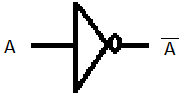
In NOT Gate, If two signal A is given to the gate, the resultant will be A
AND Gate:
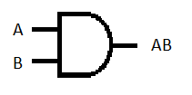
In AND Gate, If two signal A and B are given to the gate, the resultant will be AB
OR Gate:
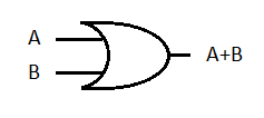
In OR Gate, If two signal A and B are given to the gate, the resultant will be A+B
We are dividing the question into two circuit to understand the inputs and outputs,
Circuit P: Signal A and B passes through different NOT gates and their resultant will be A and B
And these resultant signal goes to the AND gate as inputs and its resultant will be AB
Circuit Q: Signals A and B are passing through AND gate as two inputs, and their resultant will be AB.
Now the resultant of Circuit P and circuit Q ie, AB and AB are passing through the OR gate as input signals and the resultant will be AB+AB
This is the final output.
So the final answer is option (D), X=AB+AB.
Note: Logic gates are implemented by using transistors, diodes, relays, optics and molecules or even by several mechanical elements. Due to this reason logic gates can also be considered as electronic circuits. A table which lists out the combination of input variables and the corresponding output variables is termed as a truth table.