Question
Question: When an input signal \[1\] is applied to a NOT gate, its output is: A) \[1\] B) \[0\] C) Eithe...
When an input signal 1 is applied to a NOT gate, its output is:
A) 1
B) 0
C) Either 0 or 1
D) Both 0 and 1
Solution
NOT gate is one of the basic logical gates. It can be remembered from the name itself that NOT implies getting the opposite output. Remember all the basic gates to avoid confusion.
Complete step by step solution:
The various basic logic gates used digital systems are as follows:
1. OR Gate
2. AND Gate
3. NOT Gate
4. XOR Gate
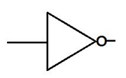
Below is the NOT gate.
OR GATE: In OR gate the output of an OR gate gives the state 1 , if one or more inputs attain the state 1 i.e. when any one input is 1 then the output will be one.
The Boolean expression of the OR gate is given as Y=A+B, which is read as Y equals A ‘OR ’ B.
AND GATE: In AND gate the output of an AND gate is 1 if and only if all the inputs are in state 1. The Boolean expression of AND gate is Y=A.B which is read as Y equals A ‘AND’ B.
NOT GATE: In NOT gate the output of a NOT gate attains the state 1 if and only if the input does not attain the state 1 . The Boolean expression is Y=A , read as Y equals NOT A.
Hence for input signal 1 the output will be 0.
Note: All basic gates must be remembered. NAND and XNOR gates are the logical gates which can be obtained using the basic OR, NOT and AND gate. Also the truth table can be easily constructed for each logical gate based on the above definitions. Truth tables make it easier to understand logical gates.