Question
Question: When a resistor R is connected in series with an element A, the electric current is found to be lagg...
When a resistor R is connected in series with an element A, the electric current is found to be lagging behind the voltage by angle θ1. When the same resistance is connected in series with element B, current leads voltage by θ2. When R, A, B are connected in series, the current now leads voltage by theta. Assume the same AC source is used in all cases then:
A.θ=θ2−θ1
B.tanθ=tanθ2−tanθ1
C.θ=2θ1−θ2
D. None of these
Solution
The lagging and leading conditions of the electric current and the voltage in the given are used to find the elements present in the circuit, that is, we will first find the type of elements A and B are. Then, we will substitute the values of the ratios obtained in first and second cases in the third case, as per the given cases.
Formula used: tanθ=RXL
tanθ=RXC
Complete step by step answer:
There are a total of 3 cases that can be considered based on the data given to us.
They are discussed as follows.
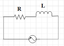
Case I : A – R circuit
In this case, a resistance R is connected in series with an element A. For this arrangement, the electric current is found to be lagging behind the voltage by an angle of the value of θ1.
Thus, the result of this arrangement is that the voltage leads. And, this type of result is only possible, when there is an inductor connected in the circuit.
Thus, the element A is considered to be an inductor.
The circuit diagram of RL.
The phasor diagram of series RL circuit
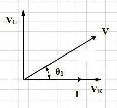
Thus, the ratio can be found to be equal to the value of, tanθ1=RXL
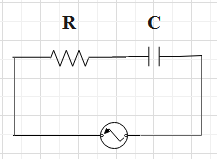
Case II : B – R circuit
In this case, a resistance R is connected in series with an element B. For this arrangement, the voltage is found to be lagging behind the electric current by an angle of the value of θ2.
Thus, the result of this arrangement is that the electric current leads. And, this type of result is only possible, when there is a capacitor connected in the circuit.
Thus, the element B is considered to be a capacitor.
The circuit diagram of RC.
The phasor diagram of the series RC circuit
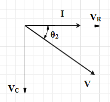
Thus, the ratio can be found to be equal to the value of, tanθ2=RXC
Case III : A – R – B circuit
In this case, a resistance R is connected in series with an element B and an element A. For this arrangement, the electric current is found to be lagging behind the voltage by an angle of the value of θ.
As we have already determined the type of elements A and B are. So, the circuit consists of a resistor R, a capacitor B and an inductor A.
The circuit diagram of RLC.
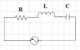
Thus, the result of this arrangement is that the electric current leads. And, this type of result is only possible, when the value of the capacitive reactance is more than that of the inductive reactance.
The phasor diagram of series RLC circuit
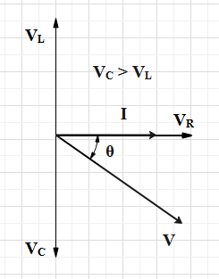
Thus, the ratio can be found to be equal to the value of, tanθ=RXC−XL.
Substitute the values of the angles of the tan function obtained in the above-discussed cases.
So, we have,