Question
Question: What will be the phase difference between input and output voltage of a common emitter circuit? \(...
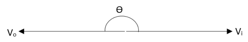
What will be the phase difference between input and output voltage of a common emitter circuit?
A.0∘B.90∘C.180∘D.270∘
Solution
The common emitter transistor circuit is defined as the one of the mainstay circuits used in the design of electronic circuits which is offering great advantages. The common emitter circuit configuration is having great use in various areas of electronic circuit design such as an audio amplifier, as a basic switch for logic circuits and so on.
Complete step by step solution:
The common emitter transistor amplifier is only an electronic circuit which will provide an inversion of 180∘between the input and output signals. The reason for this can be visualised from the fact that as the input voltage is increasing therefore the current also gets increased through the base circuit. Because of this, there will be an increase in the current through the collector circuit. That means it tends to turn the transistor on. This is the reason for the voltage between the collector and emitter terminals falling. In this manner an enhancement in the voltage between the base and emitter will be resulting in a fall in voltage between the collector and emitter terminals. In short we can say that the phase of the two signals has been inverted.
So, the correct answer is “Option C”.
Note: The common emitter circuit configuration is providing us with a voltage gain combined with a moderate current gain and also a medium output and a medium input impedance. The common emitter transistor amplifier which is inverting the signal at the input is also a primary use of this circuit. Therefore when a waveform that is rising which is entering the input of the common emitter amplifier. This will result in the output voltage to fall.