Question
Question: What is an RC Series circuit?...
What is an RC Series circuit?
Solution
In order to answer this question we need to understand that all electric or electronic circuits or structures are afflicted by a few forms of “time-put off” between it enter and output when a signal or voltage, both non-stop, (DC) or alternating (AC) is first applied to it. The resistor is a linear component whereas the inductor and capacitor have storage capacity.
Complete step by step answer:
A circuit that contains pure resistance R ohms connected in series with a pure capacitor of capacitance C farads is known as RC Series Circuit. A sinusoidal voltage is applied and current I flow through the resistance (R) and the capacitance (C) of the circuit.
The RC Series circuit is shown in the figure below:
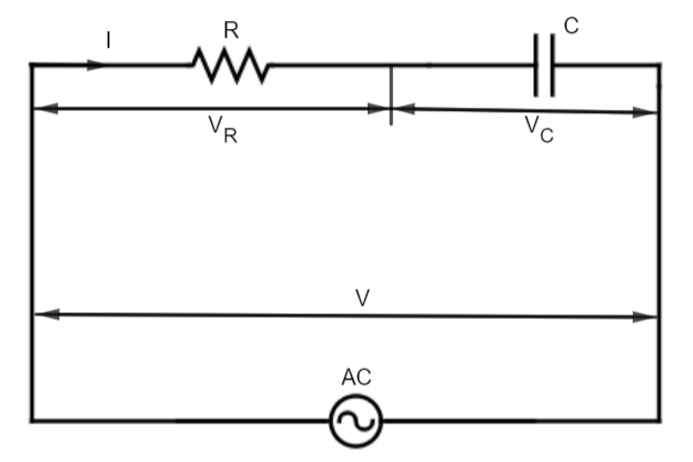
VR= voltage across the resistance R.
VC= voltage across the capacitor C.
V = total voltage across the RC series circuit.
When components R and C are in series, the current must be the same (magnitude and phase) in
all parts of the circuit. The current through the resistor R is in phase with the voltage across R.
But the capacitive current is out of phase with the capacitor voltage. IC leads VC by 90∘. Therefore, the voltages across R and C are out of phase.
Note:
It should be remembered that an RC circuit is a circuit with both a resistor (R) and a capacitor (C). A capacitor is an electrical component used to store energy by separating electric charge on two opposing plates. And a capacitor can accumulate the energy and a resistor positioned in the series will switch the rate at which it charges or discharges. And the characteristic time dependence will be exponential.