Question
Question: What is a transformer? Explain the principle, construction, working and theory of a transformer....
What is a transformer? Explain the principle, construction, working and theory of a transformer.
Solution
Hint – You can start by defining what a transformer is. Then move on to describe the principle behind the transformer. Then describe the basic setup of a transformer. Then finally write how a transformer works.
An electrical device that can change the A.C. current is known as a transformer.
Principle – A transformer works on the principle of mutual induction. Mutual induction is the phenomenon by which when the amount of magnetic flux linked with a coil changes, an E.M.F. is induced in the neighboring coil.
Construction –
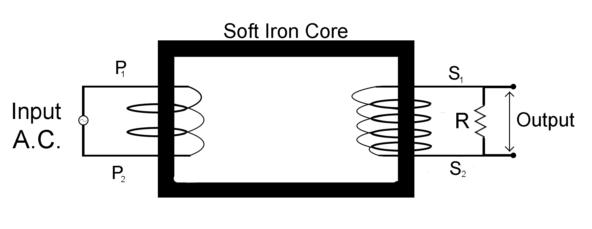
A transformer is made up of a rectangular iron core. Two coils, a primary (P) coil with two sides P1 and P2, and a secondary (S) coil with two sides S1 and S2. Both these coils are insulated from the Ferro-magnetic iron core. The source of the alternate current is connected to the primary winding and the output is obtained through the secondary winding which is connected in parallel to a resistance R.
Working -
For an ideal transformer, we consider that resistances of the primary and secondary coils are negligible.
Let the E.M.F. of the alternate current supplied by the A.C source be
EP=E0sinωt
Let’s assume that the primary winding to be a pure inductance, so here Ipwill lag behind the voltage EP by 90∘. Thus the power factor for primary coil becomes,cosϕ=cos90∘=0.
Let that the number of turns in primary wire be NP and secondary wire be NS
According to faraday law, the induced E.M.F. through one turn of both the coils will be the same.
Let the flux through one turn be ϕ, the flux through the primary coil be ϕp and the flux through the secondary coil be ϕS.
So ϕp=NPϕ
ϕS=NSϕ
We also know by Faraday’s law
E=dtdϕ
So for the primary coil this equation becomes
ES=dtdϕS(Equation 1)
And for the secondary coil this equation becomes
EP=dtdϕP(Equation 2)
Dividing equation 1 by equation 2
EPES=dϕPdϕS=NPϕNSϕ
ES=EpNpNS(Equation 3)
We know that
P=VI
Here
P=Power
V=Voltage
I=Current
For primary coil this equation becomes
PP=EPIP(Equation 4)
For secondary coil this equation becomes
PS=ESIS(Equation 5)
For an ideal transformer no energy is lost, so
Pp=PS
EPIP=ESIS
IS=IpEsEp (∵ESEp=NSNp)
IS=IpNSNp
Note – A transformer that increases the A.C. voltage is known as a step up transformer (NS>Np) and the transformer that decreases the A.C. voltage is known as a step down transformer (NS<Np). Additionally an iron core is used because it is a ferromagnetic material which helps in increasing the strength of the magnetic field.