Question
Question: Two resistors of $10\Omega$ and one $20\Omega$ resistor and an ideal inductor of $10 H$ are connecte...
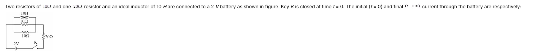
Two resistors of 10Ω and one 20Ω resistor and an ideal inductor of 10H are connected to a 2V battery as shown in figure. Key K is closed at time t=0. The initial (t=0) and final (t→∞) current through the battery are respectively:
151A,101A
101A,151A
152A,101A
151A,252A
Initial current = 252A, Final current = 101A
Solution
To determine the initial (t=0) and final (t→∞) currents through the battery, we need to analyze the behavior of the ideal inductor in the circuit at these two time instances.
Circuit Analysis:
From the given figure, the circuit consists of:
- A 2V battery.
- A 20Ω resistor (let's call it R3).
- A parallel combination of three components:
- A 10H ideal inductor (L).
- A 10Ω resistor (let's call it R1).
- Another 10Ω resistor (let's call it R2).
The 20Ω resistor (R3) is in series with this parallel combination.
1. Initial Current (at t=0):
At the instant the key K is closed (t=0), an ideal inductor behaves as an open circuit because it opposes any sudden change in current. This means no current can flow through the inductor branch at t=0.
-
Equivalent Circuit at t=0:
Since the inductor branch is open, the current flows only through the two 10Ω resistors (R1 and R2) which are in parallel.
The equivalent resistance of R1 and R2 in parallel is:
Rp,0=R1+R2R1×R2=10Ω+10Ω10Ω×10Ω=20100Ω=5Ω.
This parallel combination (Rp,0) is in series with the 20Ω resistor (R3).
The total equivalent resistance of the circuit at t=0 is:
Req,0=R3+Rp,0=20Ω+5Ω=25Ω.
-
Initial Current Calculation:
Using Ohm's Law, the initial current through the battery (Iinitial) is:
Iinitial=Req,0V=25Ω2V=252A.
2. Final Current (at t→∞):
As time approaches infinity (t→∞), the circuit reaches a steady state. In a DC steady state, an ideal inductor behaves as a short circuit (zero resistance) because the current through it becomes constant (i.e., dtdI=0, so the induced EMF LdtdI=0).
-
Equivalent Circuit at t→∞:
In the parallel combination of the 10H inductor, the 10Ω resistor (R1), and the 10Ω resistor (R2), the inductor now acts as a short circuit. When a short circuit is in parallel with other resistors, the equivalent resistance of that entire parallel combination becomes zero, as all current will flow through the path of zero resistance.
So, the equivalent resistance of the parallel part is:
Rp,∞=0Ω.
This parallel combination (now effectively a short circuit) is in series with the 20Ω resistor (R3).
The total equivalent resistance of the circuit at t→∞ is:
Req,∞=R3+Rp,∞=20Ω+0Ω=20Ω.
-
Final Current Calculation:
Using Ohm's Law, the final current through the battery (Ifinal) is:
Ifinal=Req,∞V=20Ω2V=101A.
Conclusion:
The initial current through the battery is 252A, and the final current through the battery is 101A.
The initial (t=0) and final (t→∞) current through the battery are respectively: 252A and 101A.
Explanation of the solution:
At t=0, the inductor acts as an open circuit. The two 10Ω resistors are in parallel, giving 5Ω. This 5Ω is in series with the 20Ω resistor, making total resistance 25Ω. Current = 2V/25Ω = 2/25 A.
At t→∞, the inductor acts as a short circuit. The parallel combination of inductor and two 10Ω resistors becomes a short circuit (0Ω). This 0Ω is in series with the 20Ω resistor, making total resistance 20Ω. Current = 2V/20Ω = 1/10 A.