Question
Question: Two non-ideal cells $E_1$ and $E_2$ of emf 6V and 3V respectively are connected with a variable load...
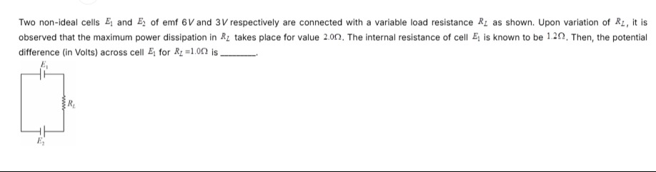
Two non-ideal cells E1 and E2 of emf 6V and 3V respectively are connected with a variable load resistance RL as shown. Upon variation of RL, it is observed that the maximum power dissipation in RL takes place for value 2.0Ω. The internal resistance of cell E1 is known to be 1.2Ω. Then, the potential difference (in Volts) across cell E1 for RL=1.0Ω is ______.
4.8
Solution
The problem involves two non-ideal cells connected in series with a variable load resistance. We need to determine the potential difference across cell E1 for a specific load resistance.
1. Analyze the Circuit Configuration: From the diagram, cell E1 has its positive terminal at the top and negative terminal at the bottom. Cell E2 has its positive terminal at the bottom and negative terminal at the top. The negative terminal of E1 is connected to the negative terminal of E2. This configuration means the cells are connected in series opposition. The net EMF (Eeq) of the combination is the difference between their EMFs. Since E1=6V and E2=3V, the net EMF is: Eeq=E1−E2=6V−3V=3V.
The direction of the current will be determined by the stronger cell, E1. Thus, the current will flow clockwise in the circuit. The total internal resistance (req) of the combination is the sum of their individual internal resistances: req=r1+r2.
2. Apply the Maximum Power Transfer Theorem: The problem states that maximum power dissipation in the load resistance (RL) occurs when RL=2.0Ω. According to the Maximum Power Transfer Theorem, maximum power is delivered to the load when the load resistance is equal to the total internal resistance of the source. Therefore, RL,max_power=req. Given RL,max_power=2.0Ω and r1=1.2Ω: 2.0Ω=r1+r2 2.0Ω=1.2Ω+r2 r2=2.0Ω−1.2Ω=0.8Ω.
So, the internal resistance of cell E2 is 0.8Ω. The total internal resistance of the equivalent battery is req=1.2Ω+0.8Ω=2.0Ω.
3. Calculate the Current for RL=1.0Ω: Now, we need to find the potential difference across cell E1 when the load resistance RL=1.0Ω. The total resistance in the circuit for this case is: Rtotal=RL+req=1.0Ω+2.0Ω=3.0Ω. The current (I) flowing through the circuit is given by Ohm's Law for the entire circuit: I=RtotalEeq=3.0Ω3V=1.0A.
4. Calculate the Potential Difference Across Cell E1: Since the current flows clockwise (driven by E1), cell E1 is discharging (current flows out of its positive terminal). The potential difference (V1) across cell E1 is given by: V1=E1−I⋅r1 V1=6V−(1.0A⋅1.2Ω) V1=6V−1.2V V1=4.8V.
The potential difference across cell E1 for RL=1.0Ω is 4.8V.