Question
Question: Two metal strips each of length l as shown are kept b apart and connected to a battery of emf Ԑ thro...
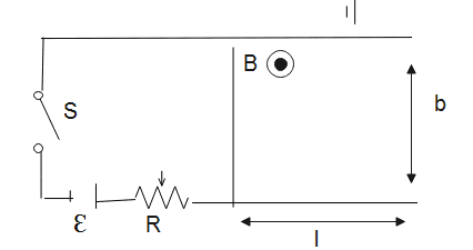
Two metal strips each of length l as shown are kept b apart and connected to a battery of emf Ԑ through a resistance R. A wire of mass m lies on it. Metal strips are smooth but the floor has coeff of friction µ. Find how far the wire will land after leaving the metal strips after the switch is made in figure.
Solution
The magnitude of the force on the current carrying conductor is given by F=IlBsinθ, here is the angle between the direction of magnetic field and the direction of flow of current. Displacement of the metal wire is further calculated by using the third equation of motion.
Formula used:
Force on a current carrying conductor F=IlBsinθ
Current in loop \eqalign{& I = \dfrac{\varepsilon }{R} \cr}
Force on an object \eqalign{& F = m \times a \cr}
Third equation of motion \eqalign{& {v^2} - {u^2} = 2as \cr}
Complete step by step answer:
The magnitude of the force on the current carrying conductor is given by F=IlBsinθ, here is the angle between the direction of magnetic field and the direction of flow of current.
Let us consider two metal strips of length l and separated by b and connected to a battery of emf Ԑ through a resistance R.
Force on the wire \eqalign{
& \vec F = IbB\overset{\lower0.5em\hbox{\smash{\scriptscriptstyle\frown}}}\to
{i} \cr}
Current in the loop
\eqalign{& I = \dfrac{\varepsilon }{R} \cr}
\eqalign{& \therefore \vec F = \dfrac{\varepsilon }{R} \times bB\overset{\lower0.5em\hbox{\smash{\scriptscriptstyle\frown}}}\to
{i} \cr}
We know from second law of motion: \eqalign{
& \vec F = ma \cr
& \Rightarrow a = \dfrac{{\vec F}}{m} = \dfrac{{\varepsilon bB}}{{mR}}\hat i \cr
& \cr}
Velocity of wire after travelling a distance on the metal strips is given by :
\eqalign{
& {v^2} - {u^2} = 2as \cr
& {v^2} - {u^2} = 2aL \cr
& {v^2} - 0 = 2\left[ {\dfrac{{\varepsilon bB}}{{mR}}} \right]L \cr}
Or,
When the wire lands on the floor, frictional force will act on it and the wire will decelerate.
a1=μg
So, deceleration due to friction is given by
Therefore, distance travelled before the wire comes to rest s is given by:
\eqalign{ & s = \dfrac{{{v^2}}}{{2a{}_1}} \cr
& s = \dfrac{{2\dfrac{{\varepsilon bB}}{{mR}}L}}{{2{\mu _g}}} \cr
& \therefore s = \dfrac{{\varepsilon bBL}}{{mR{\mu _g}}} \cr}
Therefore, when the switch is on the metal wire will land with the displacement s derived above.
Additional Information:
The magnitude of the force on the current carrying conductor is given by .
If θ=0∘ or 180∘ then F=0. Thus a current carrying conductor placed parallel to the direction of the magnetic field does not experience any force.
If θ=90∘ then Fmax=Ilb. Thus a current carrying conductor placed perpendicular to the direction of a magnetic field experiences a maximum force.
Note:
The direction of force on a current carrying conductor placed in a perpendicular magnetic field is given by Fleming’s left hand rule.
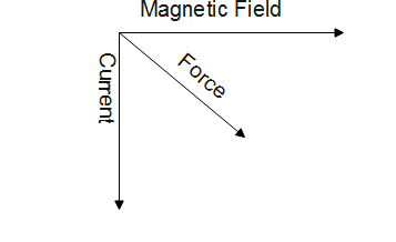
The forefinger points in the direction of the magnetic field, central finger in the direction of current, then the thumb gives the direction of force on the conductor.