Question
Question: Three identical bulbs are connected as shown in the figure. When switch S is closed, the power consu...
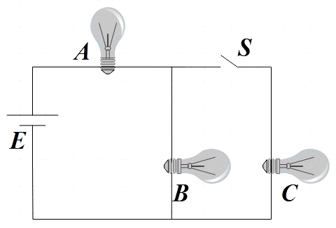
Three identical bulbs are connected as shown in the figure. When switch S is closed, the power consumed in bulb B is P. What will be the power consumed by the same bulb when switch S is opened?
A. 49P
B. 916P
C. 169P
D. 94P
Solution
Find the voltage distributed across each bulb by using voltage division rule and also, recall the expression for power in terms of R and V and thus get the expression for R. Find the effective resistance across B and C and then again apply voltage division rule to find the voltage across B. Now substitute this voltage and resistance found above in the expression for power to get the power dissipated by B.
Formula used:
Expression for power,
P=RV2
Voltage divider rule,
V1=RtotalR1V
Complete step-by-step answer:
From the circuit we see that bulbs B and C are parallel to each other and bulb A is in series with both B and C.
In the first case where the switch is put on, source voltage E is equally divided between A and parallel connection of B and C. That is, voltage across each bulb can be given by,
EA=EB=EC=2E ……………………………………… (1)
Since we are said that all the three given bulbs are identical, we could say that their resistances are also the same R.
We know that the power is given by,
P=RV2 ………………………………………. (2)
⇒R=P(2E)2=4PE2 ………………………………… (3)
Effective resistance across B and C when switch is closed is given by,
Reff=R+RR×R=2R …………………………… (4)
By voltage division rule,
VB=(2R+R)2RE
⇒VB=23R2RE=3E
Now that we got the voltage across B by voltage division rule, we could find the power dissipated by B is given by,
PB=R(3E)2
Substituting (3) we get,
PB=4PE2(3E)2
⇒PB=94P
Hence, we get the power consumed by the same bulb when switch S is opened as 94P
Hence, option D is the correct answer.
So, the correct answer is “Option D”.
Note: We also have current divider circuits that are parallel circuits in which the source or supply current divides into a number of parallel paths. So, the currents will have different values through each component. Here we have the current divider rule to calculate the current flowing through each parallel resistive branch as a percentage of the total current.