Question
Question: The wire loop- shown in the figure carries a current as shown. The magnetic field at the center O is...
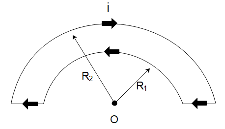
The wire loop- shown in the figure carries a current as shown. The magnetic field at the center O is:
A) zero
B) 4μ0i(R11−R21)
C) 4μ0i(R11+R21)
D) 2μ0i(R11−R21)
Solution
In this solution, we will use the formula of the magnetic field generated by a current-carrying arc at its centre. Only the curved arcs will contribute to the magnetic fields since the straight bends are carrying a current in the direction of our point.
Formula used: In this solution, we will use the following formula:
Magnetic field due to curved arc: B=2aμ0I2πθ where I is the current in the wire, θ is the angle subtended by the wire, a is the radius of the wire.
Complete step by step answer
In the diagram given to us, we can see that the wire is made up of curved portions and straight portions. Now, only the curved current-carrying portions will generate a magnetic field at the point of interest. This is because the straight wires are carrying current in a direction that passes through the point itself so there will be no magnetic field generated by the straight wire.
Both the curved portions subtend an angle of 180∘=π radians at the centre of the curves. However, both the curves are at a different distance from the centre which are respectively R1 and R2 .
Then the magnetic field due to the first curve will be
B1=2R1μ0I2ππ
⇒B1=4R1μ0I
The magnetic field due to the second curve will be
B2=2R2μ0I2ππ
⇒B2=4R2μ0I
Now since both the currents are in the opposite directions, the magnetic field generated by both these wires is in the opposite direction. Then the net magnetic field at the point will be
Bnet=4R1μ0I−4R2μ0I
⇒Bnet=4μ0I(R11−R21)
Hence the correct choice is option (B).
Note
We should realize that the straight positions of the wire will not generate a magnetic field at the centre of the curves since they carry a current in the direction of the point of interest. The magnetic field due to the closer wire will be larger since the wire is closer to the point hence from the right-hand rule, the direction of the magnetic field will be outside the page towards us.