Question
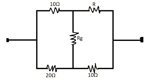
Question: The value of \( {\text{R}} \) for which no current flows through \( {{\text{R}}_{\text{g}}} \) is ...
The value of R for which no current flows through Rg is
Solution
We only need to apply the resistance concept on the following circuit. Also, it should be observed that there is a Wheatstone bridge formed.
Formula used : As required here we need Wheatstone bridge formula:
R3R1 = R4R2
Here, R1,R2,R3,R4 are the resistances of the Wheatstone bridge.
Complete step by step answer:
We know that current is not passing through the Rg resistance.
It makes the entire Wheatstone bridge.
Here, the resistances are of 10Ω , 10Ω , 20Ω , RΩ .
So, by using the above-mentioned formula:
2010=10R
⇒R=5Ω
Thus, the value of R is 5Ω .
Additional Information
The Wheatstone Bridge was originally developed by Charles Wheatstone to measure unknown resistance values and as a means of calibrating measuring instruments, voltmeters, ammeters, etc, by the use of a long resistive slide wire. Although these days, digital multimeters are provided to simplify the way to measure a resistance. The Wheatstone Bridge can still be used to measure very low values of resistances.
Note:
The Wheatstone bridge (or resistance bridge) circuit can be used in a number of applications and today, with modern operational amplifiers we can use the Wheatstone Bridge Circuit to interface various transducers and sensors to these amplifier circuits. The Wheatstone Bridge circuit is nothing more than two simple series-parallel arrangements of resistances connected between a voltage supply terminal and ground producing zero voltage difference between the two parallel branches when balanced. A Wheatstone bridge circuit has two input terminals and two output terminals consisting of four resistors configured in a diamond-like arrangement as shown. This is typical of how the Wheatstone bridge is drawn. When balanced, the Wheatstone bridge can be analysed simply as two series strings in parallel.