Question
Question: The V-I characteristics of a diode are shown in the figure. The ratio of forward to reverse bias res...
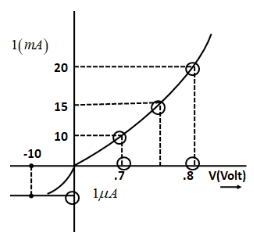
The V-I characteristics of a diode are shown in the figure. The ratio of forward to reverse bias resistance is:
A. 100
B. 10−6
C. 10
D. 106
Solution
The forward I-V characteristic, that is when the diode is forward biased, the anode is positive with respect to cathode. They given when the current is positive and the voltage is also positive. On the other hand, the reverse I-V characteristics are given when the cathode is positive with respect to anode. Here, the current is positive and the voltage is negative.
Formula Used:
Forward bias resistance Rf is given as:Rf=ΔIfΔVf
where,ΔVfis the difference between forward bias voltages,
ΔIf is the difference between currents corresponding to particular forward bias voltages.
Reverse bias resistance Rr is given as:Rr=ΔIrΔVr
where,ΔVris the difference between reverse bias voltages,
ΔIr is the difference between currents corresponding to particular reverse bias voltages.
Complete step by step answer:
The resistance offered by a diode in forward bias is very small. This is called forward resistance. On the other hand, a diode offers very high resistance when it is in reverse bias.This is called reverse resistance.
The formula for forward bias resistance Rf is given as:
{R_f} = \dfrac{{\Delta {V_f}}}{{\Delta {I_f}}}$$$$ \to ................(1)
where,ΔVfis the difference between forward bias voltages and ΔIf is the difference between currents corresponding to particular voltages.
From the given diagram, the voltages run from 0.7 Volts to 0.8 Volts. On the other hand, current ranges from 10 to 20 milli-Amperes. Therefore,
\Rightarrow \Delta {I_f} = 10mA \\\ \Rightarrow \Delta {I_f} = 10 \times {10^{ - 3}}A$$ $$\Rightarrow \Delta {V_f} = 0.8 - 0.7 \\\ \Rightarrow \Delta {V_f} = 0.1V$$ Substituting in equation (1) $${R_f} = \dfrac{{\Delta {V_f}}}{{\Delta {I_f}}} \\\ \Rightarrow {R_f} = \dfrac{{0.1}}{{10 \times {{10}^{ - 3}}}}\Omega \\\ \Rightarrow {R_f} = 10\Omega $$ The formula for reverse bias resistance $${R_r}$$ is given as: $${R_r} = \dfrac{{\Delta {V_r}}}{{\Delta {I_r}}}$$$$ \to $$................(2) where,$$\Delta {V_r}$$is the difference between reverse bias voltages and $$\Delta {I_r}$$ is the difference between currents corresponding to particular voltages. Also according to the diagram, the reverse bias current will be $${R_r} = \dfrac{{\Delta {V_r}}}{{\Delta {I_r}}} \\\ \Rightarrow {R_r} = \dfrac{{10}}{{{{10}^{ - 6}}}}\Omega \\\ \Rightarrow {R_r} = {10^7}\Omega $$ Then, the ratio of forward bias to reverse bias resistance can be written as: $$Ratio = \dfrac{{{R_f}}}{{{R_r}}} \\\ \Rightarrow Ratio = \dfrac{{10}}{{{{10}^7}}}\Omega \\\ \therefore Ratio = {10^{ - 6}}\Omega $$ **Hence, option B is the correct answer.** **Note:** The formula for reverse bias resistance and forward bias resistance can be written with the help of Ohm’s Law. Ohm’s law is given by $$V = IR$$ where $$V$$ is the voltage, $$I$$ is the current and $$R$$ is the resistance. Thus, resistance can be written as $$R = \dfrac{V}{I}$$ Thus if one writes independently in terms of forward and reverse bias resistance, this equation is, $${R_r} = \dfrac{{\Delta {V_r}}}{{\Delta {I_r}}}$$ And $${R_r} = \dfrac{{\Delta {V_r}}}{{\Delta {I_r}}}$$ respectively.