Question
Question: The three resistors configuration \({R_1},{R_2}\) and \({R_3}\) are connected to \(3V\) battery as s...
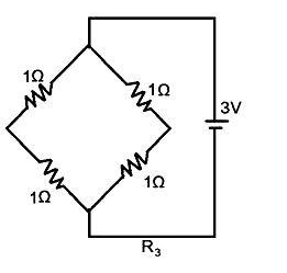
The three resistors configuration R1,R2 and R3 are connected to 3V battery as shown in figure. The power dissipated by the configuration R1,R2 and R3 is P1,P2 and P3 respectively. Then –
A) P1>P2>P3
B) P1>P3>P2
C) P2>P1>P3
D) P3>P2>P1
Solution
Hint: - Find the equivalent resistances for all the configurations in R1,R2 and R3. Now, by using the relation between power and resistance we will find the order of power in different configurations.
Complete Step by Step Solution: -
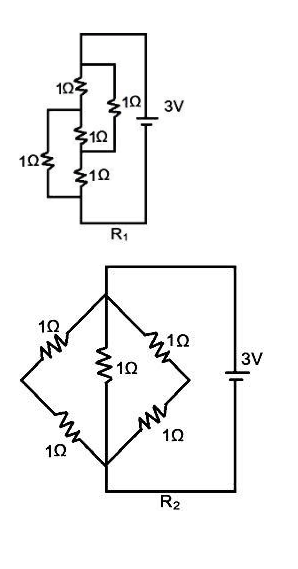
In the first configuration of R1,
From this configuration, we can conclude that there is an equivalent wheatstone bridge circuit.
∴1Ω1Ω=1Ω1Ω=1Ω
Therefore, the equivalent resistance in the configuration R1 is 1Ω.
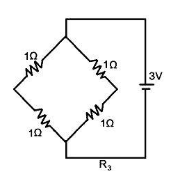
Now, we have to calculate the equivalent resistance in the configuration R2 -
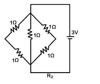
From the above figure, the equivalent resistance can be calculated by –
Therefore, the equivalent resistance in the configuration R2 is 0.5Ω.
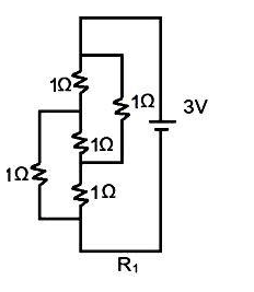
Now, we have to calculate the equivalent resistance in the configuration R3 -
From the above figure, the equivalent resistance for the configuration R3 is –
⇒R3=1+(1+1)+(1+1)(1+1)(1+1) ∴R3=1+1=2Ω
Therefore, the equivalent resistance in the configuration R3 is 2Ω.
We know that, relationship between power, voltage and resistance is –
⇒P=RV2
So, the power P1 for configuration R1 is –
⇒P1=132=9W
Power P2 for configuration R2 is –
P2=0.532=0.59 ∴P2=18W
Power P3 for configuration R3 is –
Now, we have calculated the power for each configuration for R1,R2 and R3 which are –
⇒P1=9W ⇒P2=18W ⇒P3=4.5W
Therefore, we can conclude that –
P2>P1>P3
Hence, the correct option is (C).
Note: - Wheatstone bridge is the circuit which is connected in form of the bridge and is composed of two known resistors, one unknown resistor and one variable resistor connected in the form of a bridge. This bridge gives accurate measurements, so it is most reliable. This bridge is used for the precise measurement of low resistance and is also used to measure inductance, capacitance and impedance by using the variations.