Question
Question: The supply voltage to a room is 120V. The resistance of the lead wires is \( 6\Omega \) and a 60W bu...
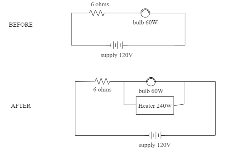
The supply voltage to a room is 120V. The resistance of the lead wires is 6Ω and a 60W bulb is already switched on. What is the decrease of voltage across the bulb, when a 240W heater is switched on in parallel to the bulb?
A. zero
B. 2.9 V
C. 13.3 V
D. 10.04 V
Solution
Hint
As voltage depends on current and resistance, the addition of any component causes it to change. It is calculated by subtracting the final voltage from the initial voltage across the component in the circuit.
⇒P=VI where P is the power generated, V is the voltage and I is the current passing through the object in consideration.
Complete step by step answer
According to the question, we have an electrical setup that draws a certain potential from the constant supply. Then, a different electrical component is added into the circuit and we have to compute the voltage drop this leads to.
We are provided with the following data:
Supply voltage V=120 V
Resistance of wire R=6 Ω
Bulb with wattage Pb=60 W
Heater in parallel with the bulb Ph=240 W
To better understand the setup, have a look at the following figure:
We first try to find the resistance of the bulb and the heater using the power law equation:
⇒P=VI=RV2 [∵I=RV]
This can also be written as:
⇒R=PV2
Putting the values of R and solving for the bulb, we get:
⇒Rbulb=601202
⇒Rbulb=240Ω
Similarly, calculating the resistance for heater, we get:
⇒Rheater=2401202
⇒Rheater=60Ω
Now, we will calculate the current across the bulb, in order to get the potential difference. Since, there are two resistances connected in series, we get the total resistance as:
⇒Rt=R+Rbulb
⇒Rt=6+240
This gives us Rt=246Ω
Hence, current through the wire will be given by:
⇒I=RtV
Putting the values and solving for I, we have:
⇒I=246120A
Using this current value, we find the voltage across the bulb:
⇒V1=I×Rbulb
⇒V1=246120×240
On calculation, we have V1=117V .
Moving on to the ‘after’ arrangement of circuit, we calculate the total resistance in parallel as this is what affects the voltage. We know that two resistances in parallel are calculated as:
⇒Rp=R1+R2R1×R2
Putting the values for Rheater and Rbulb gives us:
⇒Rp=60+24060×240
⇒Rp=30060×240
Further solving for the fractions, we get Rp=48Ω .
We know that the voltage across the parallel arrangement is the same for all components.
So, we calculate the new current that flows across the parallel circuit:
⇒I=Rp+R120
This will give us the voltage when the heater is connected as:
⇒V2=I×Rp
Putting the respective values we get,
⇒V2=48+6120×48
⇒V2=545760
Hence, potential difference across the parallel arrangement is V2=106.66V
The voltage drop, when the heater is connected, will be the difference of V1 and V2 i.e.,
⇒V1−V2=117−106.66=10.34
Upon subtraction, we get the voltage drop as 10.34V . This is approximately equal to 10.04V .
Hence, the answer is option (D) i.e. 10.04V
Note
One important concept to remember while solving circuits in series and/or parallel is how the voltage and current are distributed in the two. In a series circuit, the voltage across each component is different and depends on the resistance, while the current remains the same. But in a parallel network, the current seems to change with the components and the voltage remains constant.