Question
Question: The resistance of each branch for the arrangement shown below is R = 5 $\Omega$ and vertices are con...
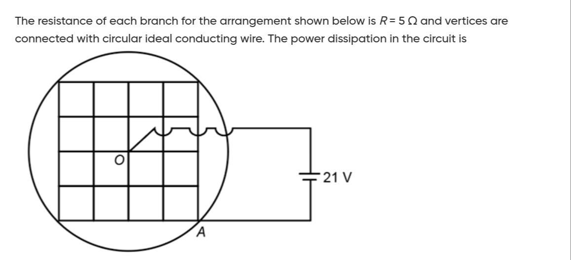
The resistance of each branch for the arrangement shown below is R = 5 Ω and vertices are connected with circular ideal conducting wire. The power dissipation in the circuit is
235.2 W
Solution
-
Identify the grid as a 4×4 array of squares, meaning 5×5 nodes.
-
The statement "vertices are connected with circular ideal conducting wire" implies all outer perimeter nodes are shorted, i.e., at the same potential.
-
Assume the battery's positive terminal is connected to the center node O=(2,2) and the negative terminal to the shorted outer boundary (which includes A=(4,4)). This assumption simplifies the problem significantly and aligns with typical grid problems.
-
Calculate the equivalent resistance (Req) between the center node and the shorted outer boundary using nodal analysis and symmetry.
-
Let VO be the potential at the center node, and 0 V at the boundary.
-
Due to symmetry, nodes at the same "distance" from the center have the same potential.
-
Nodes adjacent to O (e.g., (1,2)) are at potential V1.
-
Nodes adjacent to V1 nodes but not O or boundary (e.g., (1,1)) are at potential V2.
-
Applying Kirchhoff's Current Law (KCL) at nodes (1,2) and (1,1) (or any representative nodes for V1 and V2):
- At V1 node (e.g., (1,2)): 4V1−VO−2V2=0
- At V2 node (e.g., (1,1)): 4V2−2V1=0⟹V1=2V2
-
Solving these equations gives V2=VO/6 and V1=VO/3.
-
The total current I from O is I=R4(VO−V1)=R4(VO−VO/3)=3R8VO.
-
The equivalent resistance Req=IVO=83R.
-
-
Substitute R=5Ω: Req=83×5=815Ω.
-
Calculate power dissipation: P=ReqV2=15/8Ω(21V)2=15441×8=51176=235.2W.