Question
Question: The power factor of L – R circuit is: A) \(\dfrac{R}{{\omega L}}\) B) \(\dfrac{R}{{{{\left( {\om...
The power factor of L – R circuit is:
A) ωLR
B) (ωL)2+R2R
C) ωLR
D) ωLR
E) R2+(ωL)2R
Solution
An L – R circuit consists of a resistor and an inductor connected in series with an alternating source of voltage. The power factor of such an L – R circuit is defined as the ratio of the resistance to the impedance offered by the circuit. The impedance of a circuit is the total resistance offered by all the components in the circuit to the flow of electrons.
Formulas used:
-The power factor of an L – R circuit is given by, cosϕ=ZR where R is the resistance of the resistor and Z is the impedance offered by the circuit.
-The impedance of a series L – R circuit is given by, Z=R2+XL2 where R is the resistance and XL is the inductive reactance.
Complete step by step solution:
Step 1: Sketch a circuit diagram of the given L – R circuit.
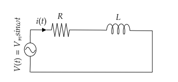
In the above L – R circuit, the resistor of resistance R and the inductor of inductance L are connected in series with the alternating voltage source.
The instantaneous voltage of the alternating source can be expressed as V(t)=Vmsinωt where Vm is the peak value of the alternating voltage, ω is the angular frequency and t is the time.
The instantaneous current through the circuit will be i(t)=imsin(ωt−ϕ) where im is the peak value of the current, ω is the angular frequency, t is the time and ϕ is the phase difference between the current and the voltage in the circuit.
The inductive reactance of the inductor in the above circuit is given by, XL=ωL .
Step 2: Express the impedance offered by the L – R circuit.
The impedance offered by the above series L – R circuit can be expressed as
Z=R2+XL2 --------- (1)
Substituting for XL=ωL in equation (1) we get the impedance offered by the circuit as Z=R2+(ωL)2 ---------- (2)
Step 3: Express the relation for the power factor of the L – R circuit.
The power factor of the given L – R circuit can be expressed as cosϕ=ZR ------- (3)
Substituting equation (2) in (3) we get, cosϕ=R2+(ωL)2R
∴ the power factor is obtained to be cosϕ=R2+(ωL)2R .
So the correct option is E.
Note: The power factor is actually the ratio of the actual power dissipation to the apparent power dissipation. If the circuit was purely resistive then the value of the power factor would be one whereas if it were a purely inductive circuit its value would be zero. In a series L – R circuit, the current lags behind the voltage. So the phase difference ϕ between the current and the voltage will be negative and the instantaneous current will be represented as i(t)=imsin(ωt−ϕ) . The current through the circuit has the same frequency as that of the applied voltage.