Question
Question: The graph given represents the I-V characteristics of a Zener Diode. Which part of the characteristi...
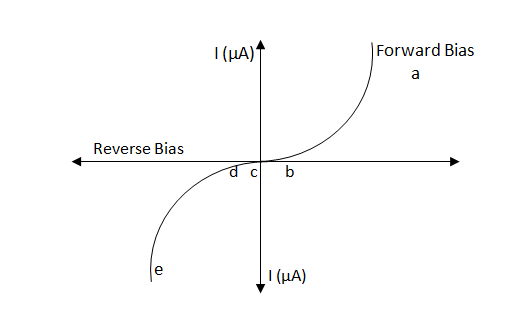
The graph given represents the I-V characteristics of a Zener Diode. Which part of the characteristic curve is most relevant for its operation as a voltage regulator?
Solution
VI characteristic graph of a p-n junction diode or Zener diode is a graph of current variation due to change in voltage. Zener diode is basically a p-n junction diode during which the doping concentration of the electrons and holes is more. It is operative in both directions, i.e. forward, and reverses bias.
Complete step-by-step solution:
In the breakdown region, Vi>Vz, for an extended range of load (RL), the voltage across RL becomes equivalent through, though the current may change. Therefore, the portion ′de′ of the characteristics curve tends to the operation of the Zener diode as the transformer.
A Zener diode works in such a way that the current can flow in both forward and reverse biased conditions. In forward bias (as shown within the ′ac′ part of the graph), there's a particular extra point in which the current increases steeply with voltage. Now it is marked as ′b′ and is understood as knee voltage. Till now (froma to b ), current increases very slowly with voltage, and after now, it starts behaving sort of a conductor, and therefore the current increases with a much higher rate. In reverse bias (as shown within the ′ce′ part of the graph), there's a particular point within the graph after which the current starts increasing with far more rate. Now it is marked and is named Zener voltage (or reverse breakdown voltage). Till now, the current is negligible and after now, the current changes at an enormous rate without much change in voltage. In fact, the difference between forward and reverse biased conditions is that in forward biased conditions, the current increases with a comparatively greater rate of order milli-ampere, and in reverse biased conditions; it increases with (micro-ampere) as shown within the graph.
Zener diode is employed to manage voltage i.e. with any amount of increase in current, the voltage change is negligible. This is often well defined within the region′de′ .
Note: Zener diodes are operated in reverse biased conditions.
Zener diodes are used for voltage regulation, surge suppressors, and in switching applications. The load voltage equals the breakdown voltage VZ of the diode.
The load voltage is equal to the diode's breakdown voltage VZ. When the diode is conducting, the series resistor limits the current through the diode and decreases the excess voltage.
When the input voltage exceeds the Zener breakdown voltage, current flows through the diode, causing a voltage drop across the resistor, which activates the SCR and causes a short circuit to ground. The short circuit blows the fuse and the load is disconnected from the power supply.
Zener diodes are used in AC waveform clipping circuits to adjust or shape the waveform. To shape the waveform or provide protection, the clipping circuit limits or clips off sections of either or both half cycles of an AC waveform.