Question
Question: The given graphs (a) and (b) represent the variation of the opposition offered by the circuit elemen...
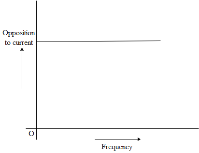
The given graphs (a) and (b) represent the variation of the opposition offered by the circuit element to the flow of alternating current, with frequency of the applied emf. Identify the circuit element corresponding to each graph.
(a)
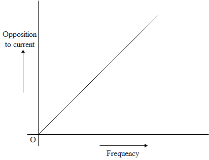
(b)
Solution
We know that the electrical resistance of a circuit component or device is defined as the ratio of the voltage applied to the electric current which flows through it: If the resistance is constant over a considerable range of voltage, then Ohm's law, I = V/R, can be used to predict the behaviour of the material. How much resistance a material has depends on several factors: the type of material, its width, its length, and its temperature. Most types of resistor are linear devices that produce a voltage drop across themselves when an electrical current flows through them because they obey Ohm's Law, and different values of resistance produce different values of current or voltage.
Complete step by step answer
It can be said that from graph (a) it is clear that resistance is not changing with frequency, resistance does not depend on frequency of applied source so the circuit element here is pure resistance. From graph (b) it is clear that resistance increases linearly with frequency so the circuit element is an inductor.
Inductive reactance, XL=2πfl
We know that in other words, an inductors electrical resistance when used in an AC circuit is called
Inductive Reactance. Inductive Reactance which is given the symbol XL, is the property in an AC circuit which opposes the change in the current. Capacitive reactance (in ohms) decreases with increasing AC frequency. Conversely, inductive reactance (in ohms) increases with increasing AC frequency. Inductors oppose faster changing currents by producing greater voltage drops; capacitors oppose faster changing voltage drops by allowing greater currents.
⇒XLαf
Note It is known that in electromagnetism and electronics, inductance is the tendency of an electrical conductor to oppose a change in the electric current flowing through it. The flow of electric current creates a magnetic field around the conductor. Inductors are primarily used in electrical power and electronic devices for these major purposes: Choking, blocking, attenuating, or filtering/smoothing high frequency noise in electrical circuits. Storing and transferring energy in power converters (dc-dc or ac-dc). Inductance is caused by the magnetic field generated by electric currents flowing within an electrical circuit. Self-inductance is the property of a circuit, often a coil, whereby a change in current causes a change in voltage in that circuit due to the magnetic effect caused by the current flow.