Question
Question: The given circuit has two ideal diodes connected as shown in the figure below. The current flowing t...
The given circuit has two ideal diodes connected as shown in the figure below. The current flowing through the resistance R1 will be:
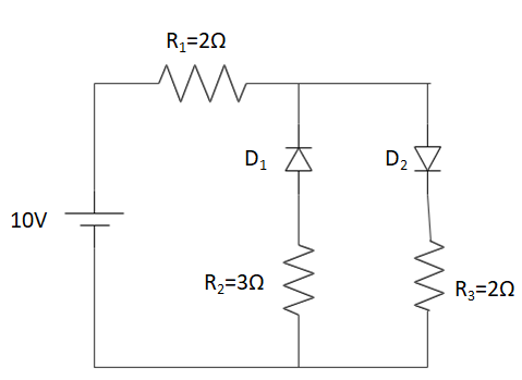
A. 3.13A
B. 2.5A
C. 10.0A
D. 1.43A
Solution
Knowledge of forward and reverse bias conditions for a pn junction diode is required. Given, since the diodes are ideal, hence the resistance of the diode will be zero in forward biasing condition and infinity in reverse biasing condition. Further, Ohm’s law would also be required to find the current value: V=IR⇒I=RV.
Complete step-by-step answer:
Let’s remake the circuit, by putting in the signs of the potential of the battery connected, the currents flowing through different arms of the circuit.
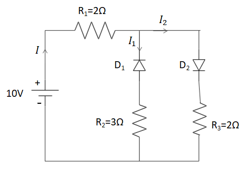
To understand the division of the current flowing through the circuit, we will use the Kirchoff’s current law. Hence, considering the amount of current to be flowing through the resistanceR1to be I. Then, the circuit breaks into two arms. Hence, the current also gets divided into I1and I2.
Hence, the sum of I1and I2will be I.
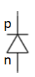
We will now discuss the diodes. A pn junction diode is a semiconductor containing excess electrons and holes on each end of the diode and a P-N junction (or) interface in between. A common region is formed in between the P and the N side having equal amounts of holes and electrons.
The P-side of the pn junction diode refers to the positive side of the semiconductor diode having holes in excess and similarly, the N-side of the pn junction diode refers to the negative side of the semiconductor diode having electrons in excess.
In this case the diode D1is connected in the reverse bias condition and the diode D2is connected in the forward bias condition. Further given in the question, we have both of these diodes to be ideal diodes. Hence, under the reverse bias condition, the resistance offered by the diode is infinity. Similarly the resistance offered by the diode in a forward bias condition is zero.
Taking this into account, there wouldn’t be any current flowing through the diodeD1. Therefore, I1=0.
Hence, I=I1+I2⇒I=I2. Therefore, the value of current flowing in the circuit can be found using the Ohm’s law: V=IR⇒10V=IRnet⇒10V=I(R1+R2)⇒10V=I(4Ω)⇒I=2.5A.
Hence, the amount of current flowing through the resistance R1 is 2.5A.
Note: We consider the value of the net resistance in the above condition to be: Rnet=R1+R2because, the resistances are in series to each other. The net resistance of the circuit, when the resistances are connected in series is given by the sum of the resistance values of the resistors connected.