Question
Question: The figure represents a voltage regulator circuit using a Zener diode. The breakdown voltage of the ...
The figure represents a voltage regulator circuit using a Zener diode. The breakdown voltage of the Zener diode is 6V and load resistance is RL=4kΩ . The series resistance of the circuit is Ri=1kΩ. If the battery voltage VB varies from 8V to 16V, what are the minimum and maximum values of the current through Zener diode?

A. 0.5mA;6mA
B. 0.5mA;8.5mA
C. 1.5mA;8.5mA
D. 1mA;8.5mA
Solution
Zener diode is a special case which is constructed differently compared to a regular PN junction diode. The property of the Zener diode that makes it special, is its constant value of voltage across several ranges.
Complete Step by Step Answer:
The Zener diode is a special purpose semiconductor diode which is named after its creator, C. Zener. It is specifically designed to operate under reverse bias conditions. The Zener diode is created by heavily doping the n and p regions.
Due to the heavy doping, the depletion region formed in the Zener diode is very small. Thus, it can breakdown at very small voltages under reverse-bias.
Here, the Zener diode is operated in Reverse Bias only. When the voltage increases, there is less response of current up to the point where the voltage breakdown happens. At this point, the voltage drop across the Zener diode remains the same even though higher amounts of current can pass through it.
Here is the given circuit:
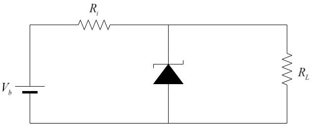
The bias voltage Vb is connected in series with series resistor Ri and the Zener diode. The load resistance has the same voltage drop as that of the Zener diode and is connected in parallel to the Zener diode as shown.
Zener breakdown voltage, Vz=6V
If the input voltage is greater than the Zener breakdown voltage, the Zener diode allows only the breakdown voltage to flow through the load and the remaining excess voltage is dropped on the series resistance connected, so as to ensure that the voltage across the load does not exceed the breakdown voltage of the Zener diode.
Case 1: When Vb=8V
Voltage drop across the series resistance, Vi=8−6=2V
Given, Ri=1kΩ
Current flowing through series resistance, Ii=RVi
Substituting, we get –
Ii=1032=2×10⁻³A=2mA
Since the voltage drop across the Zener diode and the load resistance is equal,
Current through load, IL=RLVL
Substituting, we get –
IL=4×1036=1.5×10⁻³A=1.5mA
Net current through Zener diode, Iz=Ii−IL=2−1.5=0.5mA
Case 2: When Vb=16V
Voltage drop across the series resistance, Vi=16−6=10V
Given, Ri=1kΩ
Current flowing through series resistance, Ii=RVi
Substituting, we get –
Ii=10310=10×10−3A=10mA
Since the voltage drop across the Zener diode and the load resistance is equal,
Current through load, IL=RLVL
Substituting, we get –
IL=4×1036=1.5×10⁻³A=1.5mA
Net current through Zener diode, Iz=Ii−IL=10−1.5=8.5mA
Thus,
In case 1, when Vb=8V, minimum current = 0.5mA
In case 2, when Vb=16V, maximum current = 8.5mA
∴ The minimum current is 0.5mA and the maximum current is 8.5mA. Hence, option (B) is the correct answer.
Note:
This property of Zener diodes is helpful in voltage regulation applications. Voltage regulators are used in stabiliser devices that are connected to sensitive appliances viz. television, fridge. Due to unexpected voltage surges due to lighting etc, the input voltage spikes and to protect the appliances from this surge voltage, the voltage regulator circuit is used in the stabiliser.