Question
Question: The equivalent capacitance across A and B is: (all capacitances are in \(\mu F\) ) 
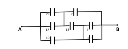
(A)328μF(B)215μF(C)15μF(D)None of these
Solution
We will first break down the above circuits into much smaller and easier to understand equivalent capacitance systems. Once, we do that we will use the formula for net capacitance in series and parallel to solve each branch step by step. And, then we can finally get the required capacitance between the two points A and B.
Complete step-by-step answer:
We will first solve the branches that are easy to solve and then simplify our circuit.
In the first step we will work on the dashed section shown in the figure below:
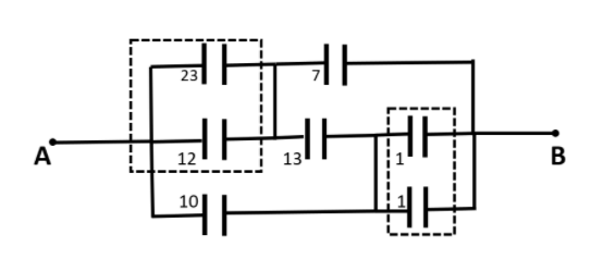
The 23μF and 12μFcapacitors are connected in parallel so their resultant could be written as 35μF . Also, when going through point B the two 1μF capacitors are connected in parallel, so their resultant will be 2μF .
Thus, our new circuit will be reconstructed as follows:
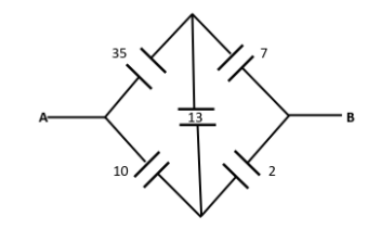
Now, this circuit looks like a wheatstone bridge. So, we will check for the condition of a balanced wheatstone bridge.
In the left-hand side of the divider capacitance, we have:
⇒L.H.S.=1035∴L.H.S.=3.5
And in the right-hand side of the divider capacitance, we have:
⇒R.H.S.=27∴R.H.S.=3.5
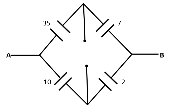
This implies that the ratio of capacitance is equal at both the sides of the divider. Thus, it is a perfectly balanced wheatstone bridge. So the divider capacitor will act as an open circuit. Thus our new circuit becomes:
The above circuit is a simple circuit having series and parallel capacitors.
In the top branch of the circuit, equivalent capacitance (sayC1 ) is equal to:
⇒C1=35+735×7μF∴C1=635μF
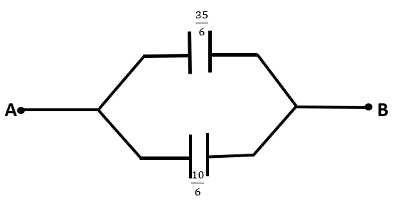
And, in the bottom branch of the circuit, equivalent capacitance (sayC2) is equal to:
⇒C2=10+210×2μF∴C2=610μF
Now, the net capacitance between A and B could be given by the summation of C1and C2as they are connected in parallel. This circuit is represented below:
Thus, the equivalent capacitance between A and B is:
⇒CAB=635+610⇒CAB=645μF∴CAB=215μF
Hence, the equivalent capacitance across A and B is 215μF.
So, the correct answer is “Option B”.
Note: In complex circuit problems like these, we should break the circuit into a smaller and easier to understand circuit at every step of the process. Also, we should keep looking for special conditions like Wheatstone bridge, as they make our problems significantly easier to solve and less complex.