Solveeit Logo

Question

Question: The e.m.f. of the cell shown in the figure is ![](https://www.vedantu.com/question-sets/b0287f3e-6...

The e.m.f. of the cell shown in the figure is

(A) 12  V12\;{\rm{V}}
(B) 13  V13\;{\rm{V}}
(C) 16  V16\;{\rm{V}}
(D) 18  V18\;{\rm{V}}

Explanation

Solution

First, we will draw the circuit diagram with current distribution in various resistance and resolve some resistance to get some idea about current flow. After this, we can apply KVL in the various loops of the circuit to determine the emf of the cell.

Complete step by step answer:
Draw the circuit diagram with the current distribution.

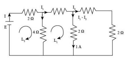
In the diagram, we resolve the two right-side resistance, which is in series. Here, we will calculate the voltage across A and B, so
VAVB=2  Ω×1  A VAVB=2  V {V_A} - {V_B} = 2\;\Omega \times 1\;{\rm{A}}\\\ \Rightarrow{V_A} - {V_B} = 2\;{\rm{V}}
Now we know that the VAVB=2  V{V_A} - {V_B} = 2\;{\rm{V}}, so calculate current I2{I_2} with the help of VAVB{V_A} - {V_B}.
Therefore, we get
2  V=I2×2  Ω I2=2  V2  Ω I2=1  A 2\;{\rm{V}} = {I_2} \times 2\;\Omega \\\ \Rightarrow{I_2} = \dfrac{{2\;{\rm{V}}}}{{2\;\Omega }}\\\ \Rightarrow{I_2} = 1\;{\rm{A}}
From the diagram we will use I1I2=  1A{I_1} - {I_2} = \;{\rm{1A}} for the determination of I1{I_1} current, so substitute the value of I2{I_2} equation.

I11  A=1  A I1=2  A{I_1} - 1\;{\rm{A}} = 1\;{\rm{A}}\\\ \Rightarrow {I_1} = 2\;{\rm{A}}

Now, we will apply the KVL in loop L1{L_1} to determine the current II.
Therefore, we get
(2  ΩI1)(2  Ω×1  A)+6  Ω(II1)=0\left( { - 2\;\Omega {I_1}} \right) - \left( {2\;\Omega \times 1\;{\rm{A}}} \right) + 6\;\Omega \left( {I - {I_1}} \right) = 0
Here, we use a negative sign where the current direction is clockwise and a positive sign where the current direction is anticlockwise in the circuit.
Substitute I1=2  A{I_1} = 2\;{\rm{A}} in the above equation.

(2    Ω×2  A)(2  Ω×1  A)+6  Ω(I2  A)=0 (4  V)(2  V)+6  ΩI12  V=0 I=18  V6  Ω I=3  A\left( { - 2\;\;\Omega \times 2\;{\rm{A}}} \right) - \left( {2\;\Omega \times 1\;{\rm{A}}} \Rightarrow\right) + 6\;\Omega \left( {I - 2\;{\rm{A}}} \right) = 0\\\ \Rightarrow \left( { - 4\;{\rm{V}}} \right) - \left( {2\;{\rm{V}}} \right) + 6\;\Omega I - 12\;{\rm{V}} = 0\\\ \Rightarrow I = \dfrac{{18\;{\rm{V}}}}{{6\;\Omega }}\\\ \Rightarrow I = 3\;{\rm{A}}

Again we will apply KVL in the loop L2{L_2} to determine the emf of the cell.
Therefore, we get
E2  ΩI6  Ω(II1)=0E - 2\;\Omega I - 6\;\Omega \left( {I - {I_1}} \right) = 0
Here, EE is the e.m.f of the cell.
Substitute the values in the above equation.

E - 2\;\Omega \left( {{\rm{3}}\;{\rm{A}}} \right) - 6\;\Omega \left( {{\rm{3}}\,{\rm{A - 2}}\;{\rm{A}}} \right) = 0\\\ \Rightarrow E - 6\;{\rm{V}} - 6\;{\rm{V}} = 0\\\ \therefore E = 12\;V$$ **Therefore, e.m.f. of the cell is $12\;{\rm{V}}$ and option (A) is correct.** **Note:** In this question, the application of KVL is an important part of the solution. So, use the correct sign convention while applying the KVL in the two loops of the circuits. If we use the wrong sign convention, then our calculation will become wrong, and we will get the incorrect value of the e.m.f of the cell.