Question
Question: The curve \(I-f\) for the anti-resonant circuit is: A. 
B. 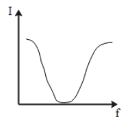
C. 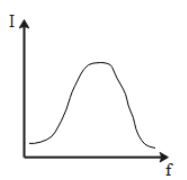
D. 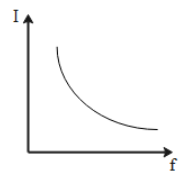
Solution
An AC source can be connected with three kinds of passive elements resistor, inductor, and capacitor. If all the three elements (resistor, inductor, and capacitor) are connected parallel to each other and the source (RLC parallel circuit) they produce a parallel resonance or anti-resonance. Such circuits are termed as anti-resonance circuits.
Complete step by step solution:
A parallel resonance circuit is the same as the series resonance circuits in many ways. Both are 3-element networks that contain two reactive components (inductor and capacitor) making the circuit a second-order circuit, both are influenced by variations in the frequency of the supply and both have a frequency point where their two reactive components cancel out each other. This influencing the characteristics of the circuit
An anti-resonant circuit is shown here,
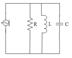
The parallel resonance circuit is influenced by the currents flowing through each branch of the parallel LC tank circuit. This tank acts as an open circuit and the value of current is equivalent to the current through the resistor only.
I=IR
The frequency of the anti-resonant circuit is the same as the value of frequency in an RLC series circuit
f=2πLC1Hz or ω=LC1rads
In the anti-resonant circuit, the value of the current is minimum at the resonant frequency. And except for the resonant point, the current in the circuit increases with an increase in the frequency.
The plot between the current and the changing frequency will be as shown in the graph here,
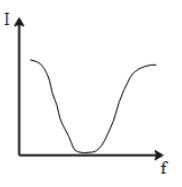
When we give a glance over the graphical representation mentioned in the question.
The option which correctly shows the graphical plot between the current and the frequency is Option B.
Note:
Both the circuits have a resonant frequency point. At this frequency, the inductor and capacitor cancel out each other’s impact. A tank circuit is a combination of L and C which are connected parallel to each other and it is used in filter networks to either select or reject AC frequencies.