Question
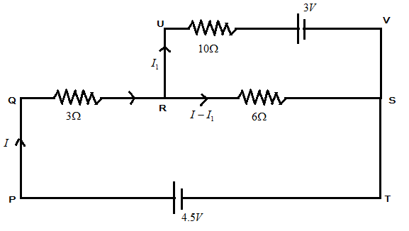
Question: The current through \( 10\Omega \) resistor as shown in fig is: 
(A) 0.1A
(B) 0.2A
(C) 0.3A
(D) zero
Solution
Hint : Here, in this question we have been asked the current flowing through the resistor of 10Ω . For this we have to study and use Kirchhoff's voltage law. It states that “in any closed loop network, the total voltage around the loop is equal to the sum of all the voltage drops within the same loop which is equal to zero”.
Complete Step By Step Answer:
let us consider the above figure and name all the voltage drops and loops for our convenience as shown in figure below:
In the figure below, let us consider the loop as PQRST by applying Kirchhoff’s voltage law to this loop, we get
−3I−6(I−I1)+4.5=0
In the above equation,
−3I is the voltage through resistor 3Ω , −6(I−I1) is the voltage through the resistor 6Ω and 4.5V is the voltage applied to the circuit.
−9I+6I1+4.5=0 ….. (1)
Now let us consider the loop PQRUVT and applying Kirchhoff’s voltage law to this loop, we get
−3I−10I1−3+4.5=0
−3I is the voltage through resistor 3Ω , −10I1 is the voltage through resistor 10Ω and 4.5V is the voltage applied to the circuit along with 3V as the voltage applied in the loop RUVSR.
−3I−10I1+1.5=0 ….. (2)
From (1) and (2) , we get
On solving both the equations we obtain the current flowing in resistor of 10Ω
I1=0
Hence, the current flowing through the resistor 10Ω is zero .
Note :
We have calculated the current flowing through the resistor 10Ω by using the Kirchhoff’s voltage law. We have used it and calculated the required answer. Voltage is the product of current and resistance through the circuit. Apply the law carefully and use the proper signs to indicate the directions of current along the circuit.