Question
Question: The current drawn from the battery by the network of resistors as shown in the figure is ...
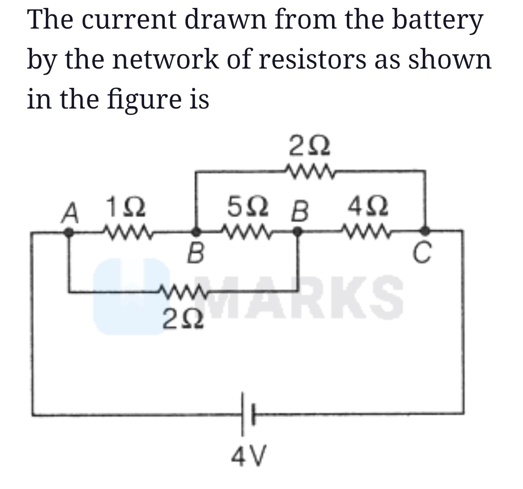
The current drawn from the battery by the network of resistors as shown in the figure is
2Ω
2A
Solution
The circuit diagram shows a network of resistors connected to a 4V battery. We need to find the total current drawn from the battery. The circuit can be analyzed using nodal analysis or by simplifying series and parallel combinations. Let's redraw the circuit and label the nodes. Let the negative terminal of the battery be at node A and the positive terminal be at node C. So, the potential difference between C and A is 4V, i.e., VC−VA=4V.
The resistors are connected as follows:
- A 1Ω resistor between A and B.
- A 2Ω resistor between A and D, where D is the junction of the 5Ω and 4Ω resistors.
- A 5Ω resistor between B and D.
- A 4Ω resistor between D and C.
- A 2Ω resistor between B and C.
The circuit diagram is a bridge-like structure. Let's calculate the equivalent resistance of the network between A and C. We can use nodal analysis. Let VA=0 V, then VC=4 V. Let the potential at node B be VB and at node D be VD.
Applying Kirchhoff's Current Law at node B:
1VA−VB+5VD−VB+2VC−VB=0
10−VB+5VD−VB+24−VB=0
−VB+5VD−VB+24−VB=0
Multiplying by 10: −10VB+2(VD−VB)+5(4−VB)=0
−10VB+2VD−2VB+20−5VB=0
−17VB+2VD+20=0⟹17VB−2VD=20 (Equation 1)
Applying Kirchhoff's Current Law at node D:
2VA−VD+5B−VD+4VC−VD=0
20−VD+5VB−VD+44−VD=0
−2VD+5VB−VD+44−VD=0
Multiplying by 20: −10VD+4(VB−VD)+5(4−VD)=0
−10VD+4VB−4VD+20−5VD=0
4VB−19VD+20=0⟹4VB−19VD=−20 (Equation 2)
Now we solve the system of linear equations for VB and VD.
From Equation 1: 2VD=17VB−20⟹VD=217VB−20
Substitute into Equation 2: 4VB−19(217VB−20)=−20
8VB−19(17VB−20)=−40
8VB−323VB+380=−40
−315VB=−420
VB=−315−420=315420=3×1054×105=34 V.
Now find VD: VD=217VB−20=217(4/3)−20=268/3−60/3=28/3=34 V.
Since VB=VD=4/3 V, the potential difference across the 5Ω resistor is VB−VD=4/3−4/3=0. This means no current flows through the 5Ω resistor. The 5Ω resistor is effectively short-circuited in terms of current flow through it, but it still affects the equivalent resistance of the network. This configuration, where the ratio of resistances in two arms is equal to the ratio of resistances in the other two arms of the bridge (excluding the bridge resistor), results in zero current through the bridge resistor. However, in our case, the ratios are RAB/RAD=1/2 and RBC/RDC=2/4=1/2. So, RADRAB=RDCRBC=21. This is a balanced Wheatstone bridge with the 5Ω resistor as the bridge resistor.
Since the bridge is balanced, the 5Ω resistor can be removed from the circuit without affecting the current distribution in the other resistors or the equivalent resistance between A and C. The circuit simplifies to: A 1Ω resistor in series with a 2Ω resistor, and this combination is in parallel with a 2Ω resistor in series with a 4Ω resistor.
Upper branch resistance: Rupper=RAB+RBC=1Ω+2Ω=3Ω.
Lower branch resistance: Rlower=RAD+RDC=2Ω+4Ω=6Ω.
These two branches are connected in parallel between A and C.
Equivalent resistance Req between A and C is:
Req1=Rupper1+Rlower1=3Ω1+6Ω1=62+61=63=21
Req=2Ω.
The total current drawn from the battery is given by Ohm's law:
I=ReqV
where V is the battery voltage (4V) and Req is the equivalent resistance (2Ω).
I=2Ω4V=2A.