Question
Question: The connections shown in figure are established with the switch S open. How much charge will flow th...
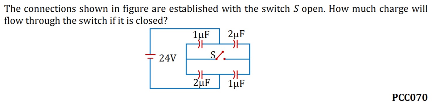
The connections shown in figure are established with the switch S open. How much charge will flow through the switch if it is closed?
0 μC
Solution
When the switch S is open, the circuit consists of a 24V battery connected in parallel to two branches. The top branch has a 1 μF capacitor (C1). The bottom branch has a 2 μF capacitor (C2).
The diagram indicates that the left plates of both capacitors are connected to the positive terminal of the battery (24V), and the right plates of both capacitors are connected to the negative terminal of the battery (0V). Therefore, when the switch is open, both capacitors are directly across the 24V battery.
The voltage across the 1 μF capacitor is V1=24V. The charge on the 1 μF capacitor is Q1=C1V1=(1μF)×(24V)=24μC.
The voltage across the 2 μF capacitor is V2=24V. The charge on the 2 μF capacitor is Q2=C2V2=(2μF)×(24V)=48μC.
When the switch S is closed, it connects the right plate of the 1 μF capacitor to the right plate of the 2 μF capacitor. The circuit configuration remains the same: both capacitors are still connected in parallel across the 24V battery.
The voltage across the 1 μF capacitor is V1′=24V. The charge on the 1 μF capacitor is Q1′=C1V1′=(1μF)×(24V)=24μC.
The voltage across the 2 μF capacitor is V2′=24V. The charge on the 2 μF capacitor is Q2′=C2V2′=(2μF)×(24V)=48μC.
The charge that flows through the switch is the difference in charge that redistributes on the plates connected by the switch. Let's consider the charge on the right plates of the capacitors. Initially (switch open), the right plates are connected to the negative terminal (0V). Charge on the right plate of C1 is q1r=−Q1=−24μC. Charge on the right plate of C2 is q2r=−Q2=−48μC.
After closing the switch, the circuit configuration does not change the voltage across the capacitors. The right plates are still effectively at 0V potential relative to the negative terminal of the battery. Charge on the right plate of C1 is q1r′=−Q1′=−24μC. Charge on the right plate of C2 is q2r′=−Q2′=−48μC.
The total charge that flows through the switch is the sum of the change in charge on the right plates: Charge flow = (q1r′−q1r)+(q2r′−q2r) = (−24μC−(−24μC))+(−48μC−(−48μC)) = 0μC+0μC=0μC.
Therefore, no charge flows through the switch when it is closed.