Question
Question: The circuit shown in figure is in steady state. What will be the potential difference across the cap...
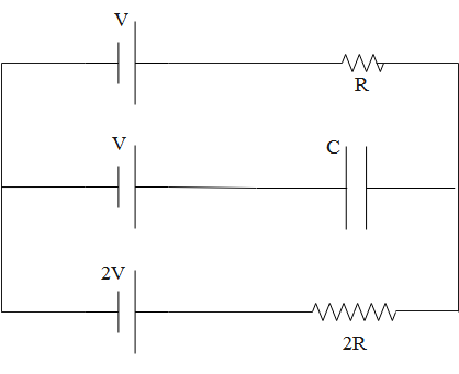
The circuit shown in figure is in steady state. What will be the potential difference across the capacitor?
A. V
B. 2V
C. 3V
D. 32V
Solution
To solve this problem, first assume the direction of current in each branch and label accordingly. Then, use Kirchhoff’s Voltage Law along closed loops and Kirchhoff’s Current law at the junction.
According to KVL, “the algebraic sum of all voltages within the loop must be equal to zero.”
According to Kirchhoff’s Current Law or KCL the total current entering at junction is exactly equal to the electric current leaving the node.
Complete answer:
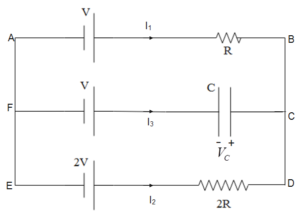
First, we name the connecting points as shown in figure below. We have assumed that current flowing along AB, ED and FC is I1,I2 and I3 respectively.
According to Kirchhoff’s Voltage Law or KVL, “in any closed loop network, the total potential difference around the loop is equal to the sum of all the potential drops within the same loop is equal to zero. In other words, “the algebraic sum of all voltages within the loop must be equal to zero.”
So, moving along the loop ABDEA, we have
−V+I1R−2I3R+2V
On simplifying this equation, we get
V=(2I3−I1)R
According to Kirchhoff’s Current Law or KCL the total current entering at junction is exactly equal to the electric current leaving the node. Therefore, at node C, we have
I1+I2+I3=0
Since, I3=0, we have
I1=−I3
Substituting this value in expression obtained for voltage, we get
V=(2I3−(−I1))R=3I3R
This implies that
I3R=3V
Let’s assume that potential difference across the capacitor is VC, then applying KVL along the loop CDEF, we get
−2I3R+2V−V−VC=0
Substituting I3R=3V, the above equation becomes
−32V+2V−V−VC
On rearranging and simplifying, we get potential difference across the capacitor as
VC=3V
So, the correct answer is “Option C”.
Note:
Kirchhoff’s laws can be used to solve most of the problems related to electric circuits.
While using Kirchhoff’s laws, signs must be used according to convention. Otherwise, students may arrive at the wrong results.
The direction of current, we assume, does not affect the magnitude of current. If we assume the direction of current in the opposite direction of its actual direction, the magnitude of current obtained will be negative.