Question
Question: If the switch remains closed for a long time and then is opened at t = 0 then which option in List-I...
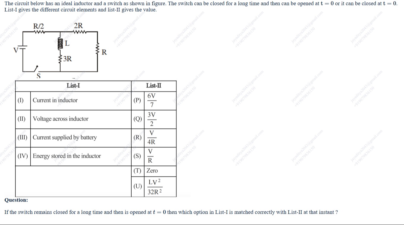
If the switch remains closed for a long time and then is opened at t = 0 then which option in List-I is matched correctly with List-II at that instant ?
76V
23V
4RV
RV
Zero
32R2LV2
The correct matches are (I)-(R), (II)-(Q), (III)-(T), and (IV)-(U).
Solution
The switch is closed for a long time, and then opened at t=0. We need to find the values of the quantities in List-I at the instant t=0+, immediately after the switch is opened.
First, let's analyze the circuit when the switch is closed for a long time (t<0, steady state). In steady state, an ideal inductor acts as a short circuit.
The circuit consists of the battery V in series with the switch S and resistor R/2. This series combination is connected across the parallel combination of two branches:
Branch 1: Inductor L in series with resistor 3R. In steady state, this branch has resistance 3R (since the inductor is a short). Branch 2: Resistors 2R and R in series, which has a total resistance of 2R+R=3R.
So, the circuit in steady state (switch closed) is the battery V in series with R/2, connected across the parallel combination of a 3R resistor and another 3R resistor.
The equivalent resistance of the parallel combination of 3R and 3R is Rp=3R+3R3R×3R=6R9R2=23R.
The total equivalent resistance seen by the battery is Req=2R+Rp=2R+23R=24R=2R.
The current supplied by the battery in steady state is Ibattery(t<0)=ReqV=2RV.
This current flows through the R/2 resistor and then splits equally between the two parallel branches because they have equal resistance (3R).
The current through the branch containing the inductor (and 3R) is the inductor current: IL(t<0)=2Ibattery(t<0)=2V/2R=4RV.
The current through the other branch (with 2R and R) is also 4RV.
Now, the switch is opened at t=0. The current through an inductor cannot change instantaneously. So, the current in the inductor immediately after the switch is opened (t=0+) is the same as the current just before the switch was opened (t=0−).
IL(t=0+)=IL(t=0−)=4RV.
When the switch is opened, the battery and the R/2 resistor are disconnected from the rest of the circuit. The remaining circuit consists of the parallel combination of the branch (inductor L in series with resistor 3R) and the branch (resistors 2R and R in series, total 3R). These two branches form a closed loop.
The initial current IL(0+)=4RV flows through the inductor and the 3R resistor in its branch. This current must return through the other branch, which consists of 2R+R=3R.
So, at t=0+, the current IL(0+)=4RV flows through the series combination of L and 3R. This current flows in a loop formed by L→3R→(2R+R)→L. The total resistance in this loop is 3R+(2R+R)=3R+3R=6R.
For t>0, the current IL(t) in the inductor decays according to the equation LdtdIL+(3R+2R+R)IL=0, which simplifies to LdtdIL+6RIL=0.
The solution is IL(t)=IL(0+)e−(6R/L)t=4RVe−(6R/L)t for t≥0.
Let's evaluate the quantities in List-I at t=0+:
(I) Current in inductor:
At t=0+, IL(0+)=4RV.
Comparing with List-II: (R) 4RV.
So, (I) matches with (R).
(II) Voltage across inductor:
The voltage across the inductor is VL(t)=LdtdIL.
VL(t)=Ldtd(4RVe−(6R/L)t)=L4RV(−L6R)e−(6R/L)t=−4R6RVe−(6R/L)t=−23Ve−(6R/L)t.
At t=0+, VL(0+)=−23Ve0=−23V.
The magnitude of the voltage is 23V. The negative sign indicates the direction of the induced voltage opposes the current flow. The question asks for the value, which could mean magnitude or signed value depending on context. Let's check the options.
(Q) 23V.
This matches the magnitude. Often, in such problems, the magnitude is expected unless a specific direction/polarity is defined in the question or figure for the voltage. Let's assume magnitude is required.
So, (II) matches with (Q).
(III) Current supplied by battery:
At t=0+, the switch is open. When the switch is open, the circuit containing the battery is broken.
Therefore, the current supplied by the battery at t=0+ is zero.
Comparing with List-II: (T) Zero.
So, (III) matches with (T).
(IV) Energy stored in the inductor:
The energy stored in the inductor at t=0+ is EL(0+)=21LIL(0+)2.
EL(0+)=21L(4RV)2=21L16R2V2=32R2LV2.
Comparing with List-II: (U) 32R2LV2.
So, (IV) matches with (U).
The question asks which option in List-I is matched correctly with List-II at that instant. This implies we need to find which combination of (List-I element, List-II value) is correct. The correct matches are (I)-(R), (II)-(Q), (III)-(T), and (IV)-(U).