Question
Question: The circuit below has an ideal inductor and a switch as shown in figure. The switch can be closed fo...
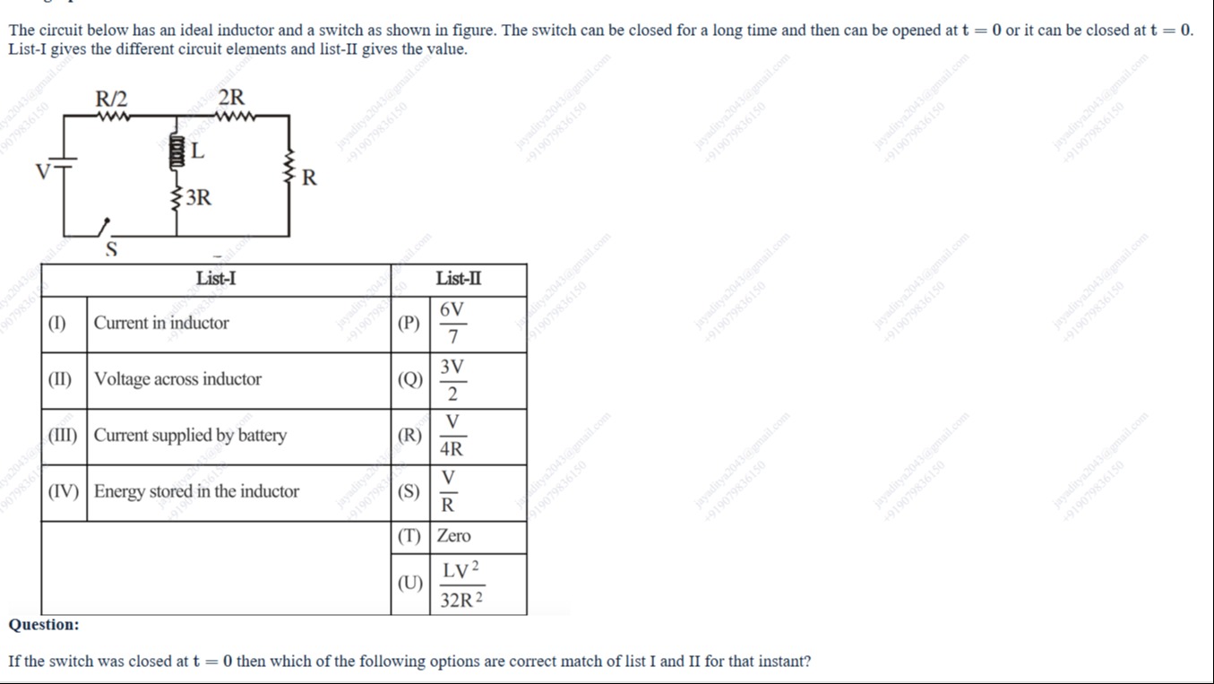
The circuit below has an ideal inductor and a switch as shown in figure. The switch can be closed for a long time and then can be opened at t = 0 or it can be closed at t = 0. List-I gives the different circuit elements and list-II gives the value.
| List-I | List-II | ||
|---|---|---|---|
| (I) | Current in inductor | (P) | 76V |
| (II) | Voltage across inductor | (Q) | 23V |
| (III) | Current supplied by battery | (R) | 4RV |
| (IV) | Energy stored in the inductor | (S) | RV |
| (T) | Zero | ||
| (U) | 32R2LV2 |
If the switch was closed at t = 0 then which of the following options are correct match of list I and II for that instant?
76V
23V
4RV
RV
Zero
32R2LV2
The correct matches are (I)-T, (II)-P, (IV)-T. The value for (III) is not in List-II.
Solution
Here's a breakdown of the solution:
Understanding the Circuit at t = 0+
When the switch is closed at t = 0, we analyze the circuit's behavior immediately after the switch closure (t = 0+). Crucially, the current through an inductor cannot change instantaneously.
Step-by-step Analysis
-
(I) Current in Inductor:
- At t = 0+, the inductor acts as an open circuit because the current through it was zero before the switch closed.
- Therefore, the current in the inductor, IL(0+)=0. This matches option (T).
-
(II) Voltage across Inductor:
- The voltage across the inductor at t = 0+ can be found by analyzing the equivalent circuit. The inductor branch (L and 3R) is in parallel with the 3R resistor (2R + R). This parallel combination is in series with the R/2 resistor, and the battery V.
- The current supplied by the battery is I=R/2+3RV=7R2V. This current flows through the 3R resistor.
- The voltage across the 3R resistor (and therefore across the inductor branch) is V3R=7R2V⋅3R=76V. Since the inductor current is zero at t=0+, the voltage across the inductor is simply the voltage across the parallel branch, which is 76V. This matches option (P).
-
(III) Current Supplied by Battery:
- As calculated above, the current supplied by the battery at t = 0+ is 7R2V. However, this value is not present in List-II.
-
(IV) Energy Stored in the Inductor:
- The energy stored in an inductor is given by E=21LI2.
- Since the current through the inductor at t = 0+ is zero, the energy stored in the inductor is also zero. This matches option (T).
Conclusion
Based on the analysis, the correct matches are (I)-T, (II)-P, and (IV)-T. The value for (III) is calculated to be 7R2V, which is not found in List-II. Therefore, we can only definitively match (I), (II), and (IV).