Question
Question: The capacitor shown in fig A2.11 is in steady state. 
The energy stored in the capacitor is
(A) CI2R2
(B) 2CI2R2
(C) 4CI2R2
(D) None of these
Solution
R is resistor, C is capacitor and I is current flowing in wire. We will now consider wire containing capacitors as current is flowing in steady state in that branch of wire. We will find energy stored in the capacitor using U=21CV2 formula where V is the potential difference across the capacitor.
Complete step by step answer
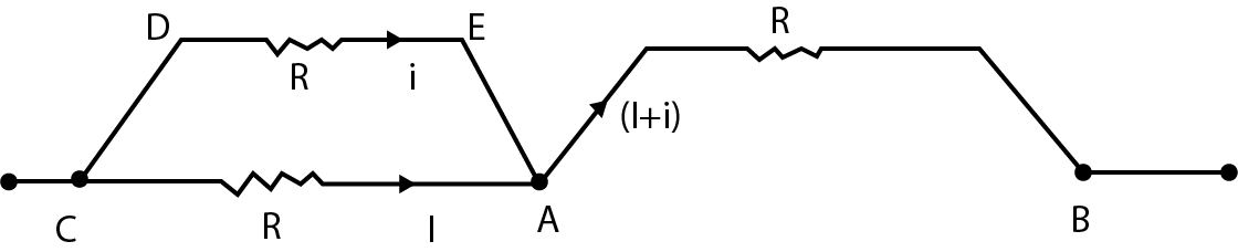
Fig A2.12.
Capacitor:
It is a two terminal device which is used to store energy in the form of an electric field. It is also known as condenser. Basically, two metallic plates are separated by a dielectric constant. S.I. unit is farad.
Resistor:
It is used to resist the flow of current. It is a passive element. S.I. unit is ohm.
Circuit:
It is a path used to conduct electricity. It consists of various elements like resistor, capacitor, wire, key, etc.
A steady state current flows through a capacitor (given). So the new circuit is as shown in fig A2.12.
Now applying loop rule or Kirchhoff’s voltage law in loop CDEAC, we get
IR=iR
⇒I=i
Now, current that flows in AB branch
AB=I+i
AB=2I
Therefore, voltage in branch AB will be
ΔV=iR
ΔVAB=2IR
Energy stored in capacitor will be
U=21CΔVAB2
U=21C(2IR)2
U=2CI2R2
Therefore, energy stored in the capacitor is 2CI2R2. So, option B is the correct
Note
If we had used energy stored formula directly without applying loop rule then instead of 2I we would have used the same current flowing in the circuit say I which is wrong. Because of which we might have got 2CI2R2 as our solution. But this won’t satisfy any option hence we would choose the option.