Question
Question: Switch S is closed at \( t = 0 \) , \( {I_{10}} \) is the current supplied by the battery just after...
Switch S is closed at t=0 , I10 is the current supplied by the battery just after closing the switch S. Q1 , Q2 and Q3 are the charges on the capacitors of 10μF , 20μF and 30μF in steady state respectively. I20 is the current supplied by the battery in the circuit at steady state. Choose the correct statement(s).
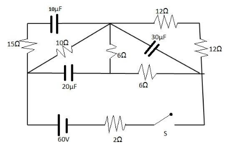
(A) I10>I20
(B) I10<I20
(C) Q1<Q2<Q3
(D) Q1<Q3<Q2
Solution
No current was flowing through the capacitors before the switch was closed at t=0 . We know that current is the flow of charge.
Formula Used: The formulae used in the solution are given here.
Current I=CdtdV , where C the capacitance in Farad and voltage across the capacitor is V .
Charge on the capacitor, Q=CV .
Complete Step by Step Solution
No flow of charge to and from the capacitors plates was zero, prior to t=0 . Hence as charge on capacitor plates varies proportionally with the voltage across them, therefore voltage across them is zero before t=0 . We can say that the capacitor was short circuited or it behaved as if it was being short circuited.
We know, current through capacitor, I and voltage across the capacitor, V , is related as
I=CdtdV , where C is the capacitance in Farad.
Following from the above, when the switch is turned on at t=0 , the capacitor behaves as being short circuited , for the initial time being.
The circuit thus looks like,
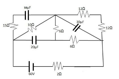
On solving, we see that the resistances 10Ω , 6Ω , 15Ω , 6Ω are in parallel. So equivalent resistance,
Req1=101+61+151+61
⇒Req1=21 .
So equivalent resistance, Req=2Ω .
There is another resistance 2Ω connected in series to the arrangement for which Req=2Ω .
Thus, resistance R=4Ω .
By Ohm’s Law, V=IR .
Thus, I10=460=15A .
At steady state, that is, after some time, the capacitor starts behaving like an open circuit.
Thus two 6Ω resistors are in parallel with two 12Ω resistors.
Equivalent resistance is thus,
Req1=2×61+2×121
⇒Req1=81
S, equivalent resistance Req=8Ω .
There are two resistances 10Ω and 2Ω connected in series to the arrangement for which Req=8Ω
By Ohm’s Law, V=IR .
At I20=2060=3A.
So I20>I10 .
Hence Option A is correct.
Now charge on the capacitor, Q=CV .
Voltage across the 10μF capacitor at steady state= 30V .
Q1=10μF×30 .
Voltage across the 20μF capacitor at steady state= 30V .
Q2=20μF×42 .
Voltage across the 30μF capacitor at steady state= 30V .
Q3=30μF×24 .
It is quite apparent, Q3>Q2>Q1 .
Hence Option D is also correct.
Note:
We can conclude that if voltage changes abruptly, current through the capacitor is spiked up. So, the tendency of the capacitor is to avoid the abrupt change in voltage across it.