Question
Question: Show by drawing labelled diagrams, the nature of output voltages in case of, -A Halfwave rectifie...
Show by drawing labelled diagrams, the nature of output voltages in case of,
-A Halfwave rectifier
-A Full Wave rectifier
-An Amplifier
(In each case, input in an ac voltage)
Circuit diagrams of these devices are not required.
Solution
The rectifiers that allow only one half of the voltage of alternating current are called Half Wave rectifiers. The rectifier that utilizes full wave of the alternating current voltage is called as Fullwave rectifiers. The replication of the input a.c voltage with a slight increase in magnitude of output wave is called as amplifiers.
Complete Step By Step Answer:
The nature of output voltages of Halfwave rectifier:
The halfwave rectifiers transform the ac voltages into dc voltages. Only one diode is used for the rectification process in the half wave rectifier. The given diagram is the positive half cycle of the a.c voltage source. The working of the rectifier when the diode is placed is as follows. When the diode is forward biased, it will act as a closed switch and when the diode is reverse biased, it will act as an open switch.
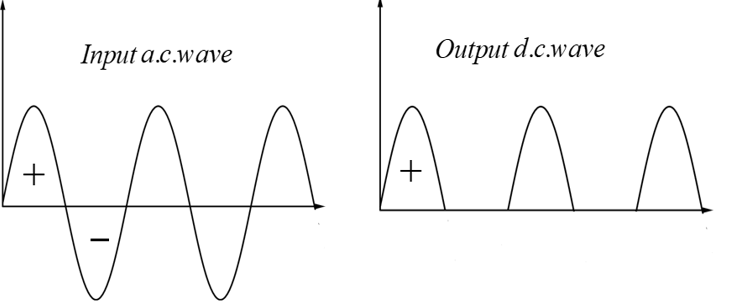
The plus sign in the diagram represents the positive half cycle of the wave and minus sign represents the negative half cycle of the wave.
The nature of output voltages of Full Wave rectifier:
The Fullwave rectifiers transform a complete cycle of alternating current into pulsating direct current. The circuit of the Fullwave rectifier is constructed using two diodes. Full wave rectifiers are not like half wave rectifiers that means unlike half wave rectifiers full wave rectifiers use the full cycle of the a.c waves. The given diagram is for the positive cycle of the diode. The lower efficiency of the half wave rectifiers can be overcome by full wave rectifiers.
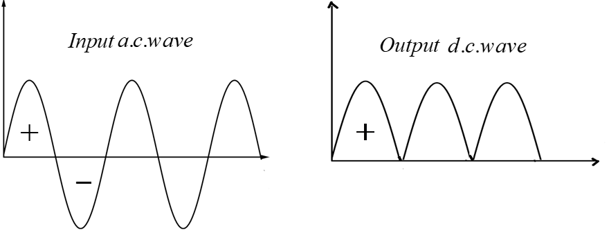
The plus sign in the diagram represents the positive half cycle of the wave and minus sign represents the negative half cycle of the wave
The nature of output voltages of Amplifiers:
The amplifiers always amplify the input a.c voltage with the increase in the magnitude of the wave and give the output wave. The given diagram is the representation of the output wave of the amplifier.
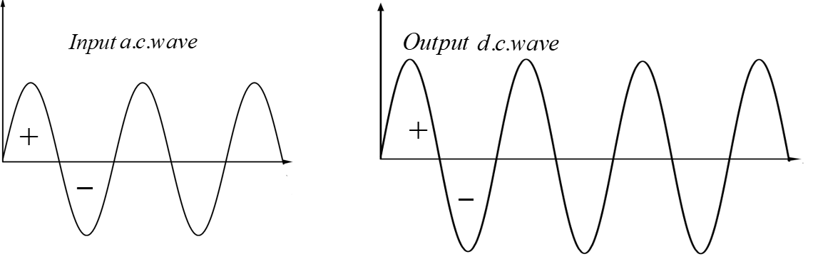
The plus sign in the diagram represents the positive half cycle of the wave and minus sign represents the negative half cycle of the wave.
Note:
The common applications of the half wave rectifiers are they are being used in the rectification process, demodulation purposes and in the signal peak applications. In the detection of the radio waves the full wave rectifiers are used. In the construction of the bridge rectifiers and in the polarized d.c voltage in the electrical welding the full wave rectifiers are used. The amplifiers are used in the selective inversion circuits, integrators, active rectifiers etc.