Question
Question: Seven resistors are connected as shown in the diagram: The equivalent resistance in ohms of this net...
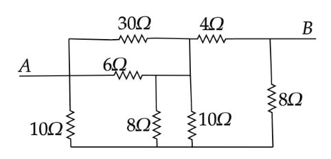
Seven resistors are connected as shown in the diagram: The equivalent resistance in ohms of this network between A and B is:
A. 6Ω
B. 8Ω
C. 12Ω
D. 20Ω
Solution
: Identify the parallel and series connection in the given circuit. First solve for the resistors in parallel connection, then the circuit will become a Wheatstone bridge. Check the condition for a balanced Wheatstone bridge.
Formula used:
Resistors connected in series, equivalence resistance Req=R1+R2+R3+...
Resistors connected in parallel, equivalence resistance Req1=R11+R21+R31+...
Complete step by step answer:
First name the resistances and redraw the circuit diagram.
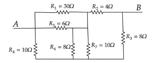
In the above circuit, we have to find the equivalent resistance between the terminal A and B.The resistors R6 and R7 are connected in parallel.Equivalence of R6 and R7 is given as
R67=R6+R7R6⋅R7
Substitute the values of R6 and R7 in the above formula.
⇒R67=8+108×10Ω
⇒R67=940Ω
The resistors R1 and R5 are connected in parallel.
The equivalent resistor of R1 and R5 is given as
R15=R1+R5R1⋅R5
Substitute the values of R1 and R5 in the above formula.
⇒R15=30+630×6Ω
⇒R15=5Ω
Now the equivalent circuit of above the circuit is as follows
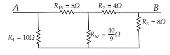
The equivalent circuit of the given circuit is a Wheatstone bridge circuit.
The Wheatstone bridge is balanced because it satisfies the condition R4R15=R3R2
Therefore, no current flows through the resistor R67. Remove the R67 from the Wheatstone bridge. The final circuit is as follows.
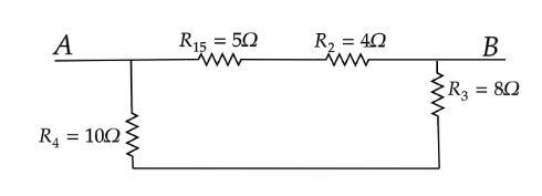
R15 and R2 are in series.
The equivalent resistance of R15 and R2 is R152=R15+R2
⇒R152=5Ω+4Ω=9Ω
R4 and R3 are in series connection.
The equivalent resistance of R4 and R3 is R45=R4+R5
⇒R45=10Ω+8Ω=18Ω
Now R152 and R45 are in parallel connection.
The equivalent resistance of R152 and R45 is Req=R152+R45R152⋅R45.
Substitute the values of R152 and R45 in the above formula.
⇒Req=9+189×18Ω
∴Req=6Ω
The equivalent resistance of the given circuit is 6Ω.
Hence the correct option is A.
Note: Alternative method:Alternatively, we can solve the circuit by drawing an equivalent circuit of the given circuit with some extra consideration as follows.
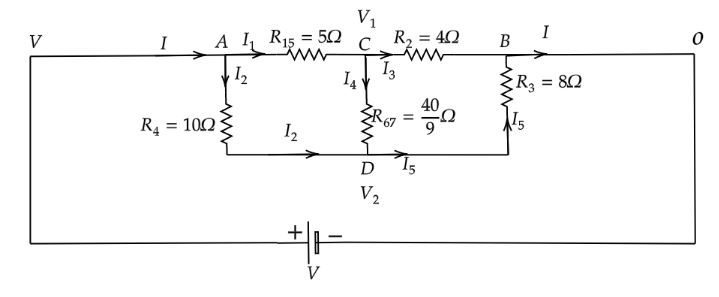
To solve the above equivalence circuit, Let the current I enter junction A and leave junction B. A battery of V voltage is connected across the terminals A and B. For simplification let terminal A is at V voltage and terminal B is at 0 voltage. Let the junctions C and D are at V1 voltage and V2 voltage respectively. Now apply Kirchhoff's current law at the junction A in the above equivalence circuit.
I=I1+I2
Apply Kirchhoff's current law at the junction C in the above equivalence circuit.
I1=I3+I4
From the above circuit diagram, I1=5V−V1
I3=4V1−0
⇒I3=4V1
⇒I4=940V1−V2
⇒I4=409(V1−V2)
Therefore,
5V−V1=4V1+409(V1−V2)
On simplification
⇒27V1−9V2=8V …… (1)
Now apply Kirchhoff's current law at junction D in the above equivalence circuit.
I2+I4=I5
From the above circuit diagram, I2=10V−V2
I5=8V2−0
⇒I5=8V2
Therefore,
10V−V2+409(V1−V2)=8V2
On simplification
⇒−9V1+18V2=4V …… (2)
Now solve the two equations (1) and (2) and find the values of V1 and V2 in terms of V. We got,
V1=94V,
⇒V2=94V
Now calculate the value of I1=5V−V1
I1=5V−94V
⇒I1=9V
And calculate the value of I2=10V−V2
I2=10V−94V
⇒I2=18V
Now we have I=I1+I2
Substitute the values of I1 and I2 in the above formula for I.
I=9V+18V
Further calculating
⇒I=6V
The equivalent resistance of the above equivalence circuit between the two terminals A and B is given by
Req=IVB−VA
Substitute all the required values in the above formula
Req=6VV−0
On further simplification
Req=6Ω
Hence the correct option is (A).