Question
Question: Determine the equivalent resistance $R_{AB}$ between points $A$ and $B$. The network is made up of ...
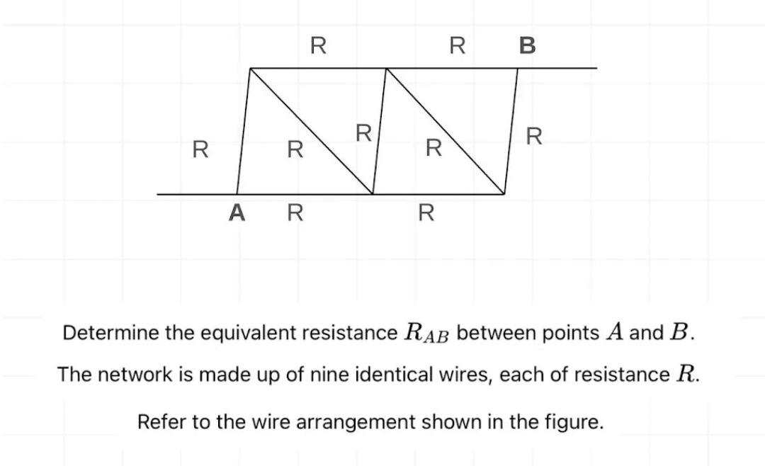
Determine the equivalent resistance RAB between points A and B.
The network is made up of nine identical wires, each of resistance R.
Refer to the wire arrangement shown in the figure.
59R
Solution
The problem asks to determine the equivalent resistance RAB between points A and B for the given network. The network consists of wires, each of resistance R. The problem statement mentions "nine identical wires", but the figure clearly shows 11 wires, each labeled with resistance R. In such cases, the diagram is usually considered the definitive representation of the circuit. We will proceed with the assumption that there are 11 wires, each of resistance R, as shown in the figure.
Let's label the nodes in the circuit for clarity:
- Bottom row nodes: A, C, D, E (from left to right)
- Top row nodes: F, G, H, B (from left to right)
The resistances are connected as follows:
- RAC=R
- RCD=R
- RDE=R
- RAF=R
- REB=R
- RFG=R
- RGH=R
- RHB=R
- RCG=R (diagonal)
- RDG=R (diagonal)
- RDH=R (diagonal)
To find the equivalent resistance RAB, we can use the node voltage method. Let's assume a potential VA=0 at node A and VB=V at node B. We need to find the total current I flowing from A to B, then RAB=V/I.
Let VC,VD,VE,VF,VG,VH be the potentials at nodes C, D, E, F, G, H respectively. Applying Kirchhoff's Current Law (KCL) at each node (sum of currents leaving the node is zero):
-
Node C: RVC−VA+RVC−VD+RVC−VG=0 Since VA=0: VC+(VC−VD)+(VC−VG)=0⟹3VC−VD−VG=0 (Eq. 1)
-
Node D: RVD−VC+RVD−VE+RVD−VG+RVD−VH=0 4VD−VC−VE−VG−VH=0 (Eq. 2)
-
Node E: RVE−VD+RVE−VB=0 Since VB=V: (VE−VD)+(VE−V)=0⟹2VE−VD−V=0 (Eq. 3) From Eq. 3, VE=2VD+V
-
Node F: RVF−VA+RVF−VG=0 Since VA=0: VF+(VF−VG)=0⟹2VF−VG=0 (Eq. 4) From Eq. 4, VF=2VG
-
Node G: RVG−VF+RVG−VC+RVG−VD+RVG−VH=0 4VG−VF−VC−VD−VH=0 (Eq. 5)
-
Node H: RVH−VG+RVH−VD+RVH−VB=0 Since VB=V: (VH−VG)+(VH−VD)+(VH−V)=0⟹3VH−VG−VD−V=0 (Eq. 6)
Now, substitute VE from Eq. 3 and VF from Eq. 4 into Eq. 2 and Eq. 5:
Substitute VE into Eq. 2: 4VD−VC−(2VD+V)−VG−VH=0 Multiply by 2: 8VD−2VC−(VD+V)−2VG−2VH=0 7VD−2VC−2VG−2VH=V (Eq. 2')
Substitute VF into Eq. 5: 4VG−(2VG)−VC−VD−VH=0 Multiply by 2: 8VG−VG−2VC−2VD−2VH=0 7VG−2VC−2VD−2VH=0 (Eq. 5')
Now we have a system of four linear equations (Eq. 1, Eq. 2', Eq. 5', Eq. 6) with four unknowns (VC,VD,VG,VH). Let's divide all equations by V and let vx=Vx/V for simplicity. So vA=0 and vB=1.
- 3vC−vD−vG=0
- −2vC+7vD−2vG−2vH=1
- −2vC−2vD+7vG−2vH=0
- −vD−vG+3vH=1
From (1), vG=3vC−vD. Substitute this into (2), (3), (4):
Substitute into (2): −2vC+7vD−2(3vC−vD)−2vH=1 −2vC+7vD−6vC+2vD−2vH=1 −8vC+9vD−2vH=1 (Eq. A)
Substitute into (3): −2vC−2vD+7(3vC−vD)−2vH=0 −2vC−2vD+21vC−7vD−2vH=0 19vC−9vD−2vH=0 (Eq. B)
Substitute into (4): −vD−(3vC−vD)+3vH=1 −vD−3vC+vD+3vH=1 −3vC+3vH=1 (Eq. C)
Now we have a system of three equations (A, B, C) with three unknowns (vC,vD,vH). From (C), 3vH=1+3vC⟹vH=31+vC. Substitute vH into (A) and (B):
Substitute into (A): −8vC+9vD−2(31+vC)=1 −8vC+9vD−32−2vC=1 −10vC+9vD=1+32=35 (Eq. A')
Substitute into (B): 19vC−9vD−2(31+vC)=0 19vC−9vD−32−2vC=0 17vC−9vD=32 (Eq. B')
Now we have a system of two equations (A', B') with two unknowns (vC,vD). Add (A') and (B'): (−10vC+9vD)+(17vC−9vD)=35+32 7vC=37 vC=31
Substitute vC=31 into (A'): −10(31)+9vD=35 −310+9vD=35 9vD=315=5 vD=95
Now find vH using vH=31+vC: vH=31+31=32
Now find vG using vG=3vC−vD: vG=3(31)−95=1−95=94
Now find vF using vF=2vG: vF=24/9=92
Now find vE using vE=2vD+1: vE=25/9+1=214/9=97
So, the potentials relative to V (where VA=0,VB=V) are: VC=V/3 VD=5V/9 VE=7V/9 VF=2V/9 VG=4V/9 VH=2V/3=6V/9
The total current I flowing from A into the network is the sum of currents through RAF and RAC: I=IAF+IAC=RVF−VA+RVC−VA I=RVF+RVC I=R2V/9+RV/3=9R2V+9R3V=9R5V
The equivalent resistance RAB is V/I: RAB=5V/(9R)V=59R
The final answer is 59R.
Explanation of the solution:
- Identify Nodes and Resistances: Label all junction points in the circuit. Count and confirm all resistances as shown in the diagram, ignoring the "nine identical wires" text if it contradicts the diagram.
- Apply Node Voltage Method: Assign a reference potential (e.g., VA=0) and an unknown potential (e.g., VB=V). Assign unknown potentials to all other independent nodes.
- Formulate KCL Equations: Write Kirchhoff's Current Law equations for each unknown node, stating that the sum of currents leaving the node is zero. This will result in a system of linear equations.
- Solve the System of Equations: Systematically solve the equations to find the potentials of all nodes in terms of V and R.
- Calculate Total Current: Determine the total current entering (or leaving) the network from the source node (A) or to the destination node (B). This is done by summing the currents through the resistors connected to the source/destination node.
- Calculate Equivalent Resistance: Use Ohm's Law RAB=V/I to find the equivalent resistance.