Question
Question: A circuit contains a resistor R = 40 $\Omega$, an inductor L = 0.5 H and a capacitor C = 0.5 mF conn...
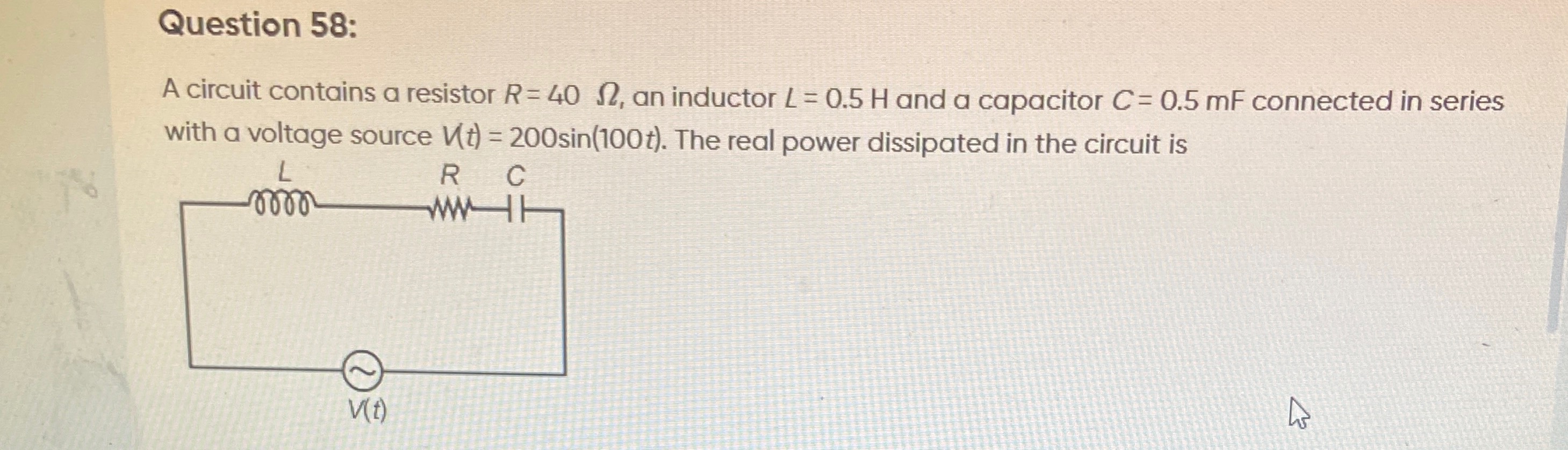
A circuit contains a resistor R = 40 Ω, an inductor L = 0.5 H and a capacitor C = 0.5 mF connected in series with a voltage source V(t)=200sin(100t). The real power dissipated in the circuit is
320 W
Solution
To determine the real power dissipated in the circuit, we follow these steps:
-
Identify the given parameters and extract angular frequency and peak voltage:
- Resistance, R=40Ω
- Inductance, L=0.5H
- Capacitance, C=0.5mF=0.5×10⁻³F
- Voltage source, V(t)=200sin(100t)
From V(t)=V0sin(ωt), we have:
- Peak voltage, V0=200V
- Angular frequency, ω=100rad/s
-
Calculate the inductive reactance (XL): XL=ωL=100rad/s×0.5H=50Ω
-
Calculate the capacitive reactance (XC): XC=ωC1=100rad/s×0.5×10−3F1=0.051=20Ω
-
Calculate the impedance (Z) of the series RLC circuit: Z=R2+(XL−XC)2
Z=402+(50−20)2
Z=402+302
Z=1600+900
Z=2500=50Ω
-
Calculate the RMS voltage (Vrms): Vrms=2V0=2200V
-
Calculate the RMS current (Irms): Irms=ZVrms=50200/2=24=22A
-
Calculate the real power (P) dissipated in the circuit:
Real power is dissipated only in the resistive component of the circuit.
P=Irms2R
P=(22)2×40
P=(4×2)×40
P=8×40
P=320W