Question
Question: The series combination of a Capacitor C and an Inductor (L = 1.0 H) is connected across an alternati...
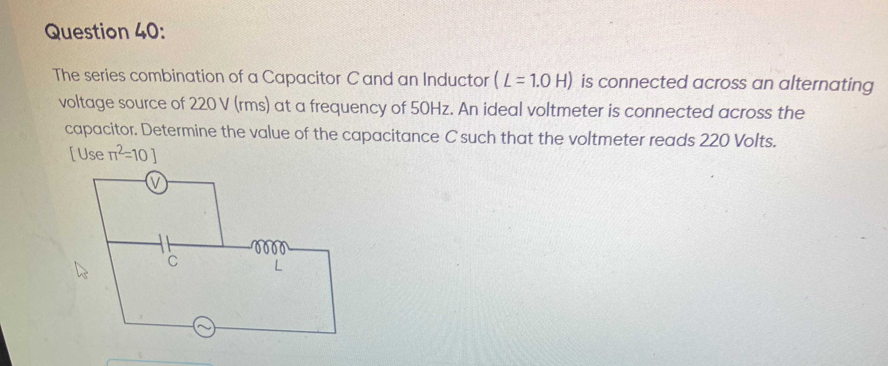
The series combination of a Capacitor C and an Inductor (L = 1.0 H) is connected across an alternating voltage source of 220 V (rms) at a frequency of 50Hz. An ideal voltmeter is connected across the capacitor. Determine the value of the capacitance C such that the voltmeter reads 220 Volts. [Use π2=10]
20 μF
Solution
The circuit consists of a capacitor (C) and an inductor (L) connected in series across an alternating voltage source. An ideal voltmeter is connected across the capacitor.
Given:
- Inductance, L=1.0 H
- RMS voltage of the source, Vrms=220 V
- Frequency of the source, f=50 Hz
- Voltmeter reading across the capacitor, VC=220 V
- Use π2=10
In a series LC circuit, the RMS voltage across the source (Vrms) is the magnitude of the difference between the RMS voltage across the inductor (VL) and the RMS voltage across the capacitor (VC), because these voltages are 180 degrees out of phase. The formula is: Vrms=∣VL−VC∣
Substitute the given values into the formula: 220=∣VL−220∣
This equation yields two possibilities for VL:
- VL−220=220⟹VL=440 V
- VL−220=−220⟹VL=0 V
Since the inductor has a non-zero inductance (L=1.0 H) and the frequency is non-zero (f=50 Hz), the inductive reactance XL=2πfL will be non-zero. If VL were 0, it would imply either XL=0 (which is not true) or the current Irms=0. If Irms=0, then VC=IrmsXC would also be 0, which contradicts the given VC=220 V. Therefore, VL=0 V is not physically possible in this scenario. So, we must have VL=440 V.
In a series circuit, the RMS current (Irms) is the same through both components. We can express the voltages across the components in terms of current and reactance: VC=IrmsXC VL=IrmsXL
From these, we can write: Irms=XCVC=XLVL
Substitute the values of VC and VL: XC220=XL440
This simplifies to: XL=2XC
Now, we substitute the formulas for inductive reactance (XL) and capacitive reactance (XC): XL=ωL=2πfL XC=ωC1=2πfC1
Substitute these into the relationship XL=2XC: 2πfL=2(2πfC1) 2πfL=πfC1
Now, solve for the capacitance C: C=2πfL⋅πf1 C=2π2f2L1
Substitute the given numerical values: f=50 Hz L=1.0 H π2=10
C=2×10×(50)2×1.01 C=20×25001 C=500001 C=5×1041 C=0.2×10⁻⁴ F C=2×10⁻⁵ F C=20×10−6 F C=20μF
The value of the capacitance C is 20μF.