Question
Question: In the LR circuit shown (consisting an ideal inductor, 3 ideal batteries and 2 resistors), what is t...
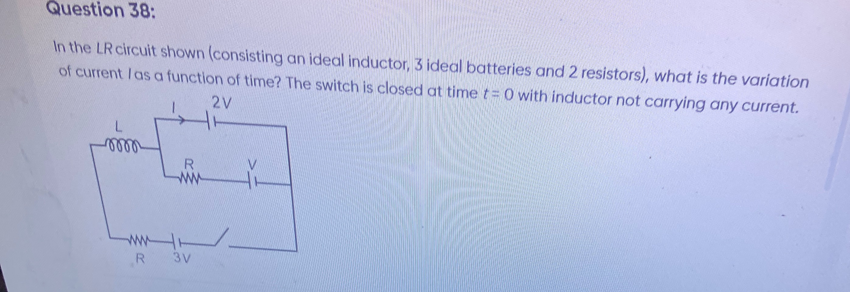
In the LR circuit shown (consisting an ideal inductor, 3 ideal batteries and 2 resistors), what is the variation of current I as a function of time? The switch is closed at time t=0 with inductor not carrying any current.
I(t) = \frac{8V}{R} (1 - e^{-Rt/(2L)})
Solution
-
Interpret the Circuit: The most plausible interpretation of the given LR circuit diagram is that the inductor L is in series with the 2V battery. This combination is then in series with a parallel combination of two branches.
- Branch 1: Top resistor R and V battery.
- Branch 2: Bottom resistor R, 3V battery, and the switch. The current I is the current flowing through the inductor L and the 2V battery.
-
Simplify the Parallel Part: Calculate the equivalent resistance (Req,p) and equivalent voltage (Veq,p) of the two parallel branches.
- For resistance: The two resistors R are in parallel, so Req,p=R+RR×R=2R.
- For voltage: Using the formula for parallel voltage sources (assuming positive terminals are aligned to contribute positively to the voltage from left to right): Veq,p=1/R1+1/R2V1/R1+V2/R2=1/R+1/RV/R+3V/R=2/R(V+3V)/R=2/R4V/R=2V.
-
Form the Equivalent Series Circuit: The entire circuit simplifies to a series combination of the inductor L, the 2V battery, the equivalent parallel resistance Req,p, and the equivalent parallel voltage Veq,p.
- Total effective voltage (Veff): The 2V battery and the Veq,p (2V) are in series. Assuming they are aiding each other (as per common circuit problem conventions for net voltage calculation), Veff=2V+2V=4V.
- Total effective resistance (Reff): The only resistance in the equivalent series circuit is Req,p=R/2. So, Reff=R/2.
-
Apply KVL to the Equivalent LR Circuit: The differential equation for current in an LR circuit is LdtdI+IReff=Veff. Substituting the values: LdtdI+I(2R)=4V.
-
Solve the Differential Equation: The solution for current in an LR circuit when the switch is closed at t=0 and initial current is zero is I(t)=Iss(1−e−t/τ).
- Steady-state current (Iss): At steady state (t→∞), the inductor acts as a short circuit. So, Iss=ReffVeff=R/24V=R8V.
- Time constant (τ): τ=ReffL=R/2L=R2L.
-
Final Expression for Current: Substitute Iss and τ into the general solution: I(t)=R8V(1−e−t/(2L/R))=R8V(1−e−Rt/(2L)).
The initial condition I(0)=0 is satisfied by this solution.
Answer: The variation of current I as a function of time is given by: I(t)=R8V(1−e−Rt/(2L))