Question
Question: Initially the circuit is in steady state. When the switch S is closed, the heat generated in the cir...
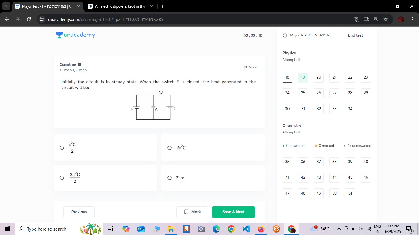
Initially the circuit is in steady state. When the switch S is closed, the heat generated in the circuit will be:
2ϵ2C
2ϵ2C
23ϵ2C
Zero
Zero
Solution
The problem asks for the heat generated in the circuit when the switch S is closed, given that the circuit is initially in a steady state with the switch S open.
-
Interpret the Circuit: The circuit consists of two identical branches connected in parallel. Each branch contains a capacitor (C) and a battery (ϵ). The negative terminals of both batteries are connected to a common ground (0V). The positive terminals of the batteries are connected to the bottom plates of their respective capacitors. The switch S connects the top plates of the two capacitors.
-
Analyze the Initial State (Switch S open):
- Since the circuit is in a steady state and the capacitors are connected directly across the batteries (positive terminal to bottom plate, negative terminal to ground), each capacitor will be fully charged.
- The potential of the bottom plate of each capacitor is ϵ (relative to ground).
- The potential difference across each capacitor is ϵ.
- Therefore, the potential of the top plate of each capacitor is Vtop=Vbottom+ϵ=ϵ+ϵ=2ϵ.
- So, in the initial state, the top plate of the left capacitor is at 2ϵ, and the top plate of the right capacitor is also at 2ϵ.
-
Analyze the Final State (Switch S closed):
- When the switch S is closed, it connects the top plates of the two capacitors.
- Since both top plates were already at the same potential (2ϵ), closing the switch does not create any potential difference between them.
- Therefore, no charge will flow through the switch or redistribute within the circuit.
- The charges on the capacitors and the energy stored in them remain unchanged.
-
Calculate Heat Generated:
- Heat generated in a circuit is due to energy dissipation, typically when charge flows through resistance.
- Since no charge flows when the switch is closed (because the potentials are already equal), no energy is dissipated as heat.
- Alternatively, using the energy conservation formula: H=Wbattery−ΔU.
- Change in stored energy, ΔU=Ufinal−Uinitial. Since no change occurs, ΔU=0.
- Work done by batteries, Wbattery. Since no charge flows through the batteries after closing the switch, Wbattery=0.
- Therefore, H=0−0=0.
The heat generated in the circuit is Zero.