Question
Question: Initially the circuit is in steady state. When the switch S is closed, the heat generated in the cir...
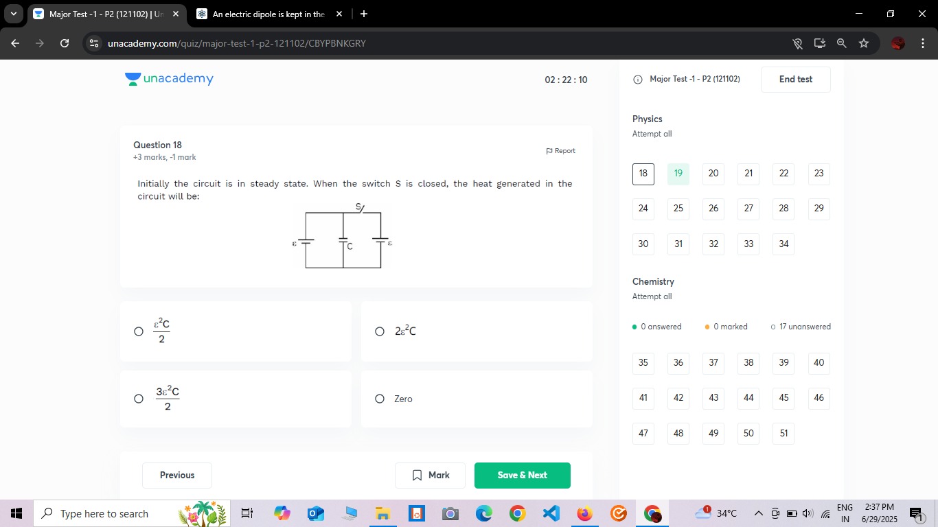
Initially the circuit is in steady state. When the switch S is closed, the heat generated in the circuit will be:
2ϵ2C
2ϵ2C
23ϵ2C
Zero
2ϵ2C
Solution
The problem asks for the total heat generated in the circuit when the switch S is closed, assuming the circuit is initially in a steady state.
1. Interpret the Circuit Diagram:
The diagram shows two batteries with EMF ϵ and a capacitor C, along with a switch S. The most plausible interpretation for such a drawing, especially in the context of capacitor problems, is that the two batteries are connected in parallel, and this parallel combination acts as the voltage source for the capacitor and the switch. The capacitor C and the switch S are connected in parallel across the terminals of this effective voltage source.
So, the circuit consists of:
- An effective voltage source of EMF ϵ (since two identical batteries in parallel provide an effective EMF equal to the individual EMF).
- A capacitor C connected across this voltage source.
- A switch S connected in parallel with the capacitor C.
2. Initial State (Switch S is open):
Initially, the switch S is open, and the circuit is in a steady state. In this state, the capacitor C is connected across the effective voltage source of EMF ϵ.
- The voltage across the capacitor is Vi=ϵ.
- The initial charge stored in the capacitor is Qi=CVi=Cϵ.
- The initial energy stored in the capacitor is Ui=21CVi2=21Cϵ2.
3. Final State (Switch S is closed):
When the switch S is closed, it creates a short circuit across the capacitor C. Since the switch S is in parallel with C, and this combination is directly connected across the voltage source, closing S effectively short-circuits the entire branch containing the capacitor and also the voltage source itself.
- The voltage across the capacitor becomes Vf=0.
- The final charge stored in the capacitor is Qf=0.
- The final energy stored in the capacitor is Uf=0.
4. Calculate Heat Generated:
The heat generated in the circuit is the total energy dissipated during the process of closing the switch until a new steady state is reached. This involves the discharge of the capacitor and the behavior of the short-circuited battery.
The energy balance equation is:
Wbattery=ΔUcapacitor+H
where Wbattery is the work done by the battery, ΔUcapacitor is the change in energy stored in the capacitor, and H is the heat generated.
-
Change in capacitor energy: ΔUcapacitor=Uf−Ui=0−21Cϵ2=−21Cϵ2. This means the capacitor releases 21Cϵ2 energy. This energy will be dissipated as heat.
-
Work done by the battery:
When the switch S is closed, the battery is short-circuited. Current flows from the positive terminal of the battery, through the switch S, and back to the negative terminal. The voltage across the battery terminals drops to zero (assuming ideal wires and switch). However, the battery still does work by moving charge.
The total charge that flows out of the battery terminals from the moment S is closed until the new steady state (where the capacitor is fully discharged and the battery is shorted) needs to be considered.
The capacitor discharges Qi=Cϵ charge. This charge flows through the switch.
In problems involving ideal batteries and short circuits, it's common to assume that the entire initial energy of the capacitor is dissipated as heat if it discharges through a "short" or a resistor. However, here the battery is also involved in the short circuit.
Let's consider the total change in charge that passes through the battery.
Initially, the battery charged the capacitor. The charge supplied by the battery to charge the capacitor was Qi=Cϵ. The work done by the battery during charging was Wcharging=Qiϵ=(Cϵ)ϵ=Cϵ2.
The heat generated during charging was Hcharging=Wcharging−Ui=Cϵ2−21Cϵ2=21Cϵ2.
Now, when the switch S is closed, the capacitor discharges. The charge Cϵ flows out of the capacitor's positive plate. This charge flows through the switch.
Simultaneously, the battery is short-circuited through the switch. This implies a continuous flow of current from the battery through the switch.
This type of problem often refers to the energy dissipated due to the change in the capacitor's state.
If we consider the energy conservation from the perspective of the entire system:
Energy supplied by battery = Change in stored energy + Heat generated.
Let's consider the total charge that passes through the battery.
When the capacitor discharges, the charge Q=Cϵ flows out of its positive plate. This charge flows through the switch.
Since the switch also short-circuits the battery, the battery will continue to supply current through the switch.
The question asks for the heat generated in the circuit when the switch is closed. This implies the heat generated during the transient process until the new steady state is reached.
If the capacitor discharges, its stored energy 21Cϵ2 is dissipated as heat. This is the heat generated by the capacitor's discharge.
However, the battery is also being short-circuited. In an ideal short circuit, infinite current flows, leading to infinite heat. This is not a realistic scenario.
Let's re-examine the options and common problem types.
Often, when a capacitor is discharged, the heat generated is equal to the initial stored energy. This is usually the case when discharging through a resistor. Here, it's discharged through a switch which also short-circuits the battery.
If the question intends to ask about the heat generated only due to the capacitor's discharge, then it would be 21Cϵ2.
However, if the battery is also short-circuited, it will continue to supply current and generate heat (if there's any resistance).
Let's consider the case where the problem implies a specific transient process.
When the switch S is closed, the voltage across the capacitor drops to zero. The capacitor discharges its initial energy Ui=21Cϵ2. This energy is dissipated as heat.
The options provided are in terms of ϵ2C.
Let's compare with the similar question. In the similar question, the heat generated during charging was 2C for V=2V, which corresponds to 21CV2.
No, the similar question states H=W−U=4C−2C=2C.
Here, W=CV2 and U=21CV2. So H=21CV2.
For V=2V, H=21C(2)2=2C. So the similar question's calculation is correct. The heat generated during charging is always equal to the energy stored in the capacitor if the battery is ideal and there is no external resistance, meaning the internal resistance of the battery or the wires dissipates the heat.
Now, in our problem:
Initial state: Capacitor charged to ϵ. Ui=21Cϵ2.
Final state: Capacitor discharged to 0. Uf=0.
When the switch is closed, the capacitor discharges. The energy it loses, ΔUcap=−21Cϵ2, is dissipated as heat. So, Hdischarge=21Cϵ2.
What about the battery? When the switch S is closed, the battery is short-circuited.
If the circuit implies that the switch S only short-circuits the capacitor C, but the battery still maintains its voltage across the circuit, that would be a different interpretation.
However, the way it's drawn, S is in parallel with C, and this combination is across the battery. So closing S short-circuits both.
Let's assume the question is about the heat generated by the capacitor as it discharges.
If a charged capacitor is short-circuited, all its stored energy is dissipated as heat.
So, H=Ui=21Cϵ2.
Let's consider if there's any work done by the battery in this process.
When the switch is closed, the capacitor discharges. The charge Cϵ flows through the switch.
The battery is also short-circuited. If we assume ideal components, this leads to an undefined current.
However, in practical scenarios, there's always some resistance.
Consider a different interpretation of the circuit diagram:
The two batteries are in series, providing a total EMF of 2ϵ.
The capacitor C is connected across this 2ϵ.
The switch S is connected in parallel with C.
If this is the case:
Initial state: C is charged to Vi=2ϵ.
Ui=21C(2ϵ)2=21C(4ϵ2)=2Cϵ2.
When S is closed, it short-circuits C.
Uf=0.
Heat generated = Ui−Uf=2Cϵ2. This is one of the options.
Let's evaluate the drawing of the batteries. They are drawn side-by-side, with positive terminals connected together and negative terminals connected together (implied by the common horizontal lines). This strongly suggests parallel connection. If they were in series, they would typically be drawn end-to-end.
So, the interpretation of parallel batteries (effective EMF ϵ) seems more likely.
If effective EMF is ϵ:
Ui=21Cϵ2.
When S is closed, it short-circuits C. The heat generated would be 21Cϵ2. This is also an option.
Why would the answer be 2ϵ2C or 23ϵ2C?
Let's consider the possibility of a different initial state.
"Initially the circuit is in steady state."
If S is open, and batteries are in parallel, VC=ϵ. Ui=21Cϵ2.
If S is closed, VC=0. Uf=0.
Heat generated by capacitor discharge is 21Cϵ2.
What if the problem is a variation of the capacitor charging problem, where a charged capacitor is discharged into another circuit?
The key is the "heat generated in the circuit".
Let's assume there is a resistor R in series with the battery and the parallel combination of C and S.
The diagram does not show any resistor. We usually assume ideal wires and components unless specified.
However, heat generation implies some resistance.
Consider the energy conservation for the entire process from initial steady state to final steady state.
Initial state: Capacitor charged to ϵ. Ui=21Cϵ2.
Final state: Capacitor discharged (shorted). Uf=0.
During the discharge, the charge Cϵ flows through the switch. This charge also flows through the battery if the battery is part of the discharge path.
If the battery is short-circuited, it will continue to supply current as long as its internal resistance allows.
Let's reconsider the similar problem.
It calculated heat generated during charging: H=Wbattery−Ucapacitor.
Wbattery=QV=CV2.
Ucapacitor=21CV2.
H=CV2−21CV2=21CV2.
For V=2V, H=21C(2)2=2C. This is the heat generated during the charging process.
Our question is about heat generated when the switch is closed.
If the switch is closed, the capacitor discharges. The energy 21Cϵ2 is dissipated.
Let's assume the question is designed to test the understanding of energy dissipation during capacitor discharge.
When a charged capacitor is allowed to discharge (e.g., by short-circuiting it), all its stored energy is converted into heat (and possibly some electromagnetic radiation, but mainly heat in a resistive circuit).
So, if the capacitor is initially charged to ϵ and then discharged, the heat generated is 21Cϵ2. This is one of the options.
What if the problem implies a scenario where the battery also contributes significantly to the heat?
If the battery is short-circuited through the switch, it will continuously supply current (if non-ideal) and generate heat. This process would continue indefinitely until the battery is depleted, which is not a typical "heat generated" question in a transient circuit.
Therefore, the most reasonable interpretation is that the heat generated refers to the energy dissipated during the discharge of the capacitor.
The initial energy stored in the capacitor is Ui=21Cϵ2.
When the switch S is closed, the capacitor discharges completely, and all this stored energy is dissipated as heat in the circuit (e.g., in the resistance of the wires, switch, or internal resistance of the battery).
Thus, the heat generated in the circuit is equal to the initial energy stored in the capacitor.
H=Ui=21Cϵ2.
The final answer is 2ϵ2C.
Explanation of the solution:
-
Initial State Analysis: The circuit consists of two batteries of EMF ϵ connected in parallel, forming an effective voltage source of ϵ. A capacitor C is connected in parallel with a switch S across this voltage source. Initially, the switch S is open, and the circuit is in a steady state. This means the capacitor C is fully charged to the voltage of the source, which is ϵ. The initial energy stored in the capacitor is Ui=21Cϵ2.
-
Final State Analysis: When the switch S is closed, it creates a short circuit across the capacitor C. This causes the capacitor to discharge completely. The final energy stored in the capacitor is Uf=0.
-
Heat Generated: When a charged capacitor discharges, all its stored energy is dissipated as heat in the circuit (e.g., in the resistance of the wires, switch, or internal resistance of the battery, even if not explicitly shown). The heat generated is equal to the energy lost by the capacitor. Heat generated, H=Ui−Uf=21Cϵ2−0=21Cϵ2.
The short-circuiting of the battery by the switch implies continuous power dissipation if the components are ideal, which is not typical for a "heat generated" question for a transient. Therefore, the question most likely refers to the heat generated due to the capacitor's discharge.
The final answer is 2ϵ2C