Question
Question: The figure shows three infinite thin non-conducting charged plates perpendicular to the plane of the...
The figure shows three infinite thin non-conducting charged plates perpendicular to the plane of the paper with charge per unit area +σ, +2σ and –3σ. As we move from plate 1 to plate 2 magnitude of potential change occur is V12, that from plate 2 to 3 is V23 and that from plate 1 to 3 is V13. Then-
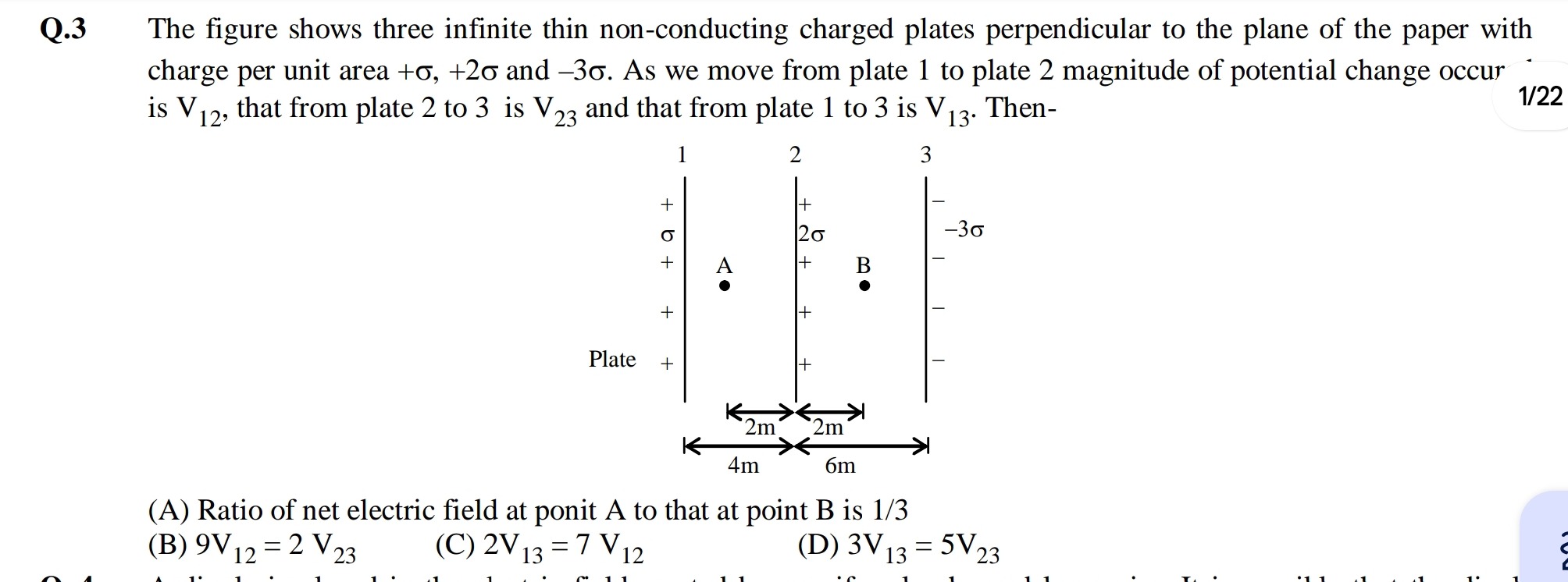
Ratio of net electric field at ponit A to that at point B is 1/3
9V12=2V23
2V13=7V12
3V13=5V23
Ratio of net electric field at ponit A to that at point B is 1/3
Solution
The problem involves calculating electric fields and potential differences due to three infinite thin non-conducting charged plates.
1. Electric Field due to a single infinite non-conducting charged plate:
The electric field magnitude due to a single infinite non-conducting charged plate with surface charge density σs is given by E=2ϵ0∣σs∣. The direction of the field is away from a positively charged plate and towards a negatively charged plate.
Let's define E0=2ϵ0σ.
The plates are:
- Plate 1: +σ
- Plate 2: +2σ
- Plate 3: −3σ
Let's set up a coordinate system where Plate 1 is at x=0, Plate 2 at x=2m, and Plate 3 at x=4m. We'll consider the right direction as positive.
Electric field contributions from each plate:
- E1: Due to Plate 1 (+σ). Field is E0 (i.e., 2ϵ0σ) away from Plate 1.
- E2: Due to Plate 2 (+2σ). Field is 2E0 (i.e., 2ϵ02σ=ϵ0σ) away from Plate 2.
- E3: Due to Plate 3 (−3σ). Field is 3E0 (i.e., 2ϵ03σ) towards Plate 3.
Net Electric Field in different regions:
-
Region I (x < 0, Left of Plate 1):
- E1: Left (−E0)
- E2: Left (−2E0)
- E3: Right (+3E0)
- Enet,I=−E0−2E0+3E0=0
-
Region II (0 < x < 2m, Between Plate 1 and Plate 2, where Point A is):
- E1: Right (+E0)
- E2: Left (−2E0)
- E3: Right (+3E0)
- Enet,II=+E0−2E0+3E0=2E0=ϵ0σ (rightward)
- Magnitude of electric field at A: ∣EA∣=ϵ0σ.
-
Region III (2m < x < 4m, Between Plate 2 and Plate 3, where Point B is):
- E1: Right (+E0)
- E2: Right (+2E0)
- E3: Right (+3E0)
- Enet,III=+E0+2E0+3E0=6E0=ϵ03σ (rightward)
- Magnitude of electric field at B: ∣EB∣=ϵ03σ.
-
Region IV (x > 4m, Right of Plate 3):
- E1: Right (+E0)
- E2: Right (+2E0)
- E3: Left (−3E0)
- Enet,IV=+E0+2E0−3E0=0
2. Evaluate Option (A): Ratio of net electric field at point A to that at point B.
∣EA∣=ϵ0σ
∣EB∣=ϵ03σ
Ratio ∣EB∣∣EA∣=3σ/ϵ0σ/ϵ0=31.
So, Option (A) is correct.
3. Calculate Potential Changes:
The potential difference between two points is given by ΔV=Vfinal−Vinitial=−∫initialfinalE⋅dl. For a uniform electric field in a region, ΔV=−ExΔx.
-
Magnitude of potential change from Plate 1 to Plate 2 (V12):
- Movement is from x=0 to x=2m. The electric field in this region (Region II) is Enet,II=ϵ0σ (rightward).
- V2−V1=−Enet,II×(2m)=−ϵ0σ×2=−ϵ02σ.
- V12=∣V2−V1∣=ϵ02σ.
-
Magnitude of potential change from Plate 2 to Plate 3 (V23):
- Movement is from x=2m to x=4m. The electric field in this region (Region III) is Enet,III=ϵ03σ (rightward).
- V3−V2=−Enet,III×(2m)=−ϵ03σ×2=−ϵ06σ.
- V23=∣V3−V2∣=ϵ06σ.
-
Magnitude of potential change from Plate 1 to Plate 3 (V13):
- This is the sum of potential changes from 1 to 2 and 2 to 3.
- V3−V1=(V3−V2)+(V2−V1)=−ϵ06σ−ϵ02σ=−ϵ08σ.
- V13=∣V3−V1∣=ϵ08σ.
4. Evaluate Options (B), (C), (D):
-
Option (B): 9V12=2V23
- LHS: 9V12=9×ϵ02σ=ϵ018σ
- RHS: 2V23=2×ϵ06σ=ϵ012σ
- 18=12. So, Option (B) is incorrect.
-
Option (C): 2V13=7V12
- LHS: 2V13=2×ϵ08σ=ϵ016σ
- RHS: 7V12=7×ϵ02σ=ϵ014σ
- 16=14. So, Option (C) is incorrect.
-
Option (D): 3V13=5V23
- LHS: 3V13=3×ϵ08σ=ϵ024σ
- RHS: 5V23=5×ϵ06σ=ϵ030σ
- 24=30. So, Option (D) is incorrect.
Based on the calculations, only Option (A) is correct.