Question
Question: Find the potential difference $V_a - V_b$ between the points a and b shows in each parts of the figu...
Find the potential difference Va−Vb between the points a and b shows in each parts of the figure.
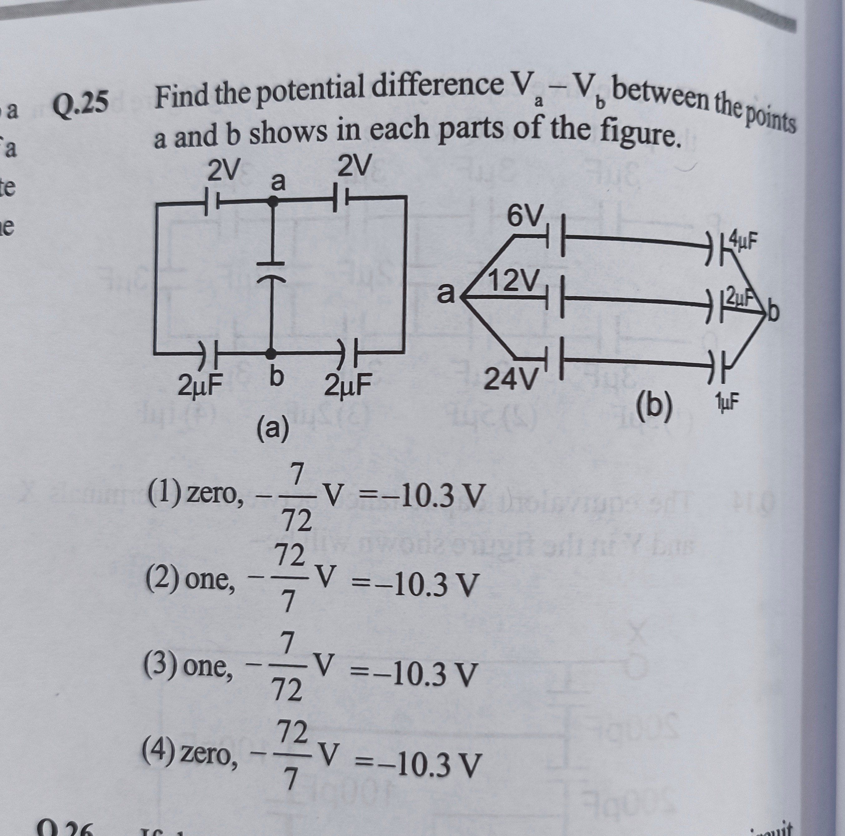
zero, −727V=−10.3V
one, −772V=−10.3V
one, −727V=−10.3V
zero, −772V=−10.3V
(4)
Solution
Part (a):
The circuit in part (a) is interpreted as a balanced Wheatstone bridge of capacitors. Assuming the labels "2V" are typos for "2μF", all four arms of the bridge (top-left, top-right, bottom-left, bottom-right) have capacitors of 2 μF.
For a capacitor bridge, the balance condition is Ctop−left/Cbottom−left=Ctop−right/Cbottom−right.
Here, 2μF/2μF=2μF/2μF, which simplifies to 1=1. Since the bridge is balanced, the potential difference between points 'a' and 'b' is zero. Va−Vb=0.
Part (b):
The circuit in part (b) is a combination of capacitors and voltage sources. We can use node analysis to find the potential difference Va−Vb. Let's assume the potential at point 'b' is 0V (Vb=0).
The charge on each capacitor is given by Q=CΔV, where ΔV is the potential difference across the capacitor. For a capacitor in series with a battery, the potential difference across the capacitor is Va−(Vb−E) if the positive terminal of the battery is closer to 'b'.
The sum of charges on the isolated node 'a' must be zero in the steady state.
- Top branch (4 μF, 6V): The potential at the end of the 6V battery closer to 'b' is Vb−6=0−6=−6V. The charge on the 4 μF capacitor is Q1=4μF×(Va−(−6V))=4(Va+6).
- Middle branch (2 μF, 12V): The potential at the end of the 12V battery closer to 'b' is Vb−12=0−12=−12V. The charge on the 2 μF capacitor is Q2=2μF×(Va−(−12V))=2(Va+12).
- Bottom branch (1 μF, 24V): The potential at the end of the 24V battery closer to 'b' is Vb−24=0−24=−24V. The charge on the 1 μF capacitor is Q3=1μF×(Va−(−24V))=1(Va+24).
Applying charge conservation at node 'a' (sum of charges on plates connected to 'a' is zero):
Q1+Q2+Q3=0
4(Va+6)+2(Va+12)+1(Va+24)=0
4Va+24+2Va+24+Va+24=0
7Va+72=0
7Va=−72
Va=−772V
Since Vb=0V, the potential difference Va−Vb=−772V.
Numerically, −772V≈−10.2857V≈−10.3V.
Combining the results for (a) and (b), the potential differences are 0 and −772V.