Question
Question: Q. 83: To enhance the sensitivity, an Ammeter is to be designed with two kinds of graduation on its ...
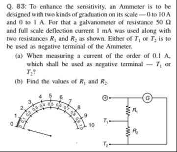
Q. 83: To enhance the sensitivity, an Ammeter is to be designed with two kinds of graduation on its scale - 0 to 10 A and 0 to 1 A. For that a galvanometer of resistance 50 Ω and full scale deflection current 1 mA was used along with two resistances R1 and R2 as shown. Either of T1 or T2 is to be used as negative terminal of the Ammeter.
(a) When measuring a current of the order of 0.1 A, which shall be used as negative terminal – T1 or T2?
(b) Find the values of R1 and R2.
(a) T2
(b) R1≈0.00500Ω, R2≈0.0450Ω
Solution
The problem describes the design of a multi-range ammeter using a galvanometer and two resistances, R1 and R2. The ammeter has two ranges: 0 to 10 A and 0 to 1 A. We are given the galvanometer's resistance (Rg) and full-scale deflection current (Ig).
Given values:
Galvanometer resistance, Rg=50Ω
Full-scale deflection current of galvanometer, Ig=1mA=1×10⁻³A
Circuit Interpretation:
The diagram shows a common positive terminal ('+') and two selectable negative terminals (T1 and T2). This is a common configuration for a multi-range ammeter where the galvanometer is in parallel with a shunt resistance, and the shunt resistance changes depending on the selected range.
Let's analyze the shunt resistance for each range:
-
When T1 is used as the negative terminal:
The total current enters at '+' and exits at T1.
From the diagram, the galvanometer (G) is in parallel with the resistance R1.
So, the shunt resistance for this range is Rsh1=R1. -
When T2 is used as the negative terminal:
The total current enters at '+' and exits at T2.
From the diagram, the galvanometer (G) is in parallel with the series combination of R1 and R2.
So, the shunt resistance for this range is Rsh2=R1+R2.
Relating ranges to terminals:
For an ammeter, a smaller shunt resistance allows a larger current to be measured (higher range), as more current is bypassed from the galvanometer. Conversely, a larger shunt resistance allows a smaller current to be measured (lower range).
Since R1<(R1+R2), the shunt resistance R1 corresponds to the higher current range, and the shunt resistance (R1+R2) corresponds to the lower current range.
Therefore:
- Using T1 as the negative terminal corresponds to the 0 to 10 A range.
- Using T2 as the negative terminal corresponds to the 0 to 1 A range.
(a) When measuring a current of the order of 0.1 A, which shall be used as negative terminal – T1 or T2?
A current of 0.1 A is best measured using the 0 to 1 A range for higher accuracy and sensitivity. As determined above, the 0 to 1 A range uses T2 as the negative terminal.
(b) Find the values of R1 and R2.
The principle for an ammeter is that the voltage across the galvanometer and the shunt resistance is the same at full-scale deflection.
IgRg=(Imax−Ig)Rsh
Where Imax is the full-scale current for the specific range.
For the 10 A range (using T1):
Imax1=10A
Rsh1=R1
IgRg=(Imax1−Ig)R1
(1×10⁻³A)×(50Ω)=(10A−1×10⁻³A)R1
0.05=(9.999)R1
R1=9.9990.05
R1≈0.0050005Ω
For the 1 A range (using T2):
Imax2=1A
Rsh2=R1+R2
IgRg=(Imax2−Ig)(R1+R2)
(1×10⁻³A)×(50Ω)=(1A−1×10⁻³A)(R1+R2)
0.05=(0.999)(R1+R2)
R1+R2=0.9990.05
R1+R2≈0.05005005Ω
Now, we can find R2:
R2=(R1+R2)−R1
R2=0.9990.05−9.9990.05
R2=0.05(0.9991−9.9991)
R2=0.05(0.999×9.9999.999−0.999)
R2=0.05(9.9890019)
R2=9.9890010.45
R2≈0.04504955Ω
Rounding to a reasonable number of significant figures (e.g., 3-4):
R1≈0.00500Ω
R2≈0.0450Ω
(a) Answer:
For measuring a small current like 0.1 A, the 0-1 A range is more sensitive and accurate than the 0-10 A range. In this ammeter design, the 0-1 A range is achieved by using T2 as the negative terminal, which places a larger shunt resistance (R1+R2) in parallel with the galvanometer, allowing less current to bypass the galvanometer for a given total current.
(b) Answer:
The values of R1 and R2 are calculated using the shunt formula Rsh=Imax−IgIgRg. For the 10 A range, the shunt is R1. For the 1 A range, the shunt is R1+R2. Solving these two equations simultaneously yields the values for R1 and R2.