Question
Question: Obtain an expression for the e.m.f induced in coil rotating in uniform magnetic field....
Obtain an expression for the e.m.f induced in coil rotating in uniform magnetic field.
Solution
Hint: Induced emf is generated in a rotating coil when the angle between area vector and magnetic field changes continuously, hence changing the amount of magnetic flux through the coil. We will find the flux through the rotating coil and the rate of change of change of magnetic flux (differentiation of flux vector with time) gives the expression for induced electromotive force through the coil.
Formula used:
ϕ=B⋅S
ε=−Ndtdϕ
Complete step by step answer:
Electromotive force is defined as the electrical action produced by a non-electrical source. Devices provide emf by converting other forms of energy into electrical energy. Examples of such devices are batteries and generators. Electromotive force or emf is the amount of energy per unit electric charge which is imparted by energy source.
EMF or electromotive force is said to be induced when the flux linking with a conductor or coil changes. This change in flux can be obtained in two different ways, either by statically or by dynamically induced emf.
Faraday's law of electromagnetic induction says that the EMF induced in a coil e= - (rate of change of magnetic flux linkage).
The factors affecting induced emf in a coil are:
Number of turns N- The induced emf is directly proportional to the number of turns in the coil.
Area of cross section S- The induced emf is directly proportional to the area of cross section of the coil.
Magnetic field B – The induced emf is directly proportional to the strength of the magnetic field in which coil is rotating.
Angular velocity ω- The induced emf is directly proportional to the angular velocity of the rotating coil.
The induced emf also varies with time and depends on the instantt.
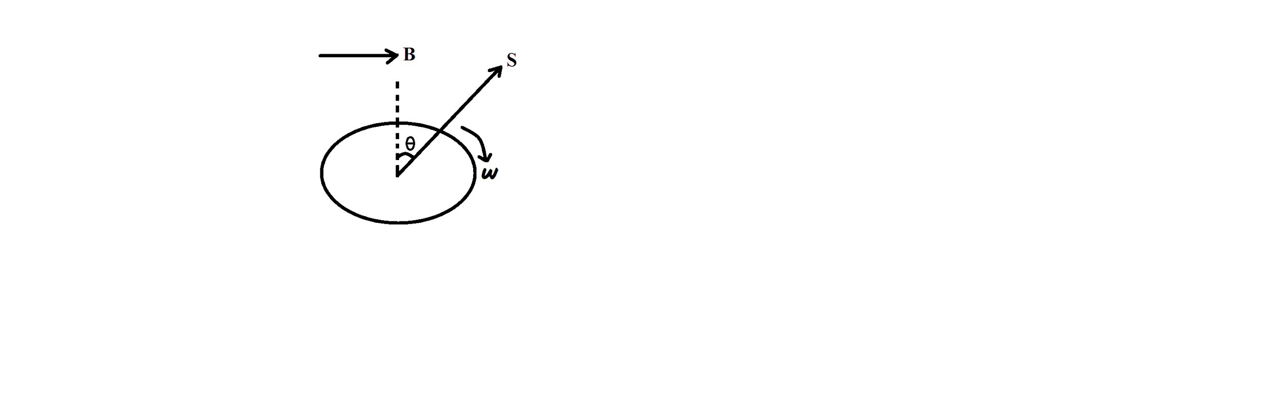
Consider a conducting coil of N turns and area S rotating with a uniform angular velocity ω about an axis in the plane of the coil, and perpendicular to a uniform magnetic field of induction B.
The frequency of rotation of the coil is,
f=2πω
Magnetic flux through the loop in the given position is given by:
ϕ=B⋅S=BScos(2π−θ)=BSsin(θ)
We have, θ=θo+ωt
Therefore, ϕ=BSsin(θo+ωt)
Induced emf is given by,
ε=−Ndtdϕ
Pitting ϕ=BSsin(θo+ωt)
ε=−Ndtd(ϕ=BSsin(θo+ωt))
ε=−NBSωcos(θo+ωt)
Therefore, the e.m.f induced in coil rotating in uniform magnetic field is given by ε=−NBSωcos(θo+ωt).
Note: The nature of the induced emf for a conductor, such as coil, rotating in the uniform magnetic field is alternating. As the conductor rotates in a magnetic field, the voltage component at various positions is different. Thus, the basic nature of induced emf is alternating.