Question
Question: Two blocks A and B each of mass m = 4 Kg, are connected by means of a pulley string system on a smoo...
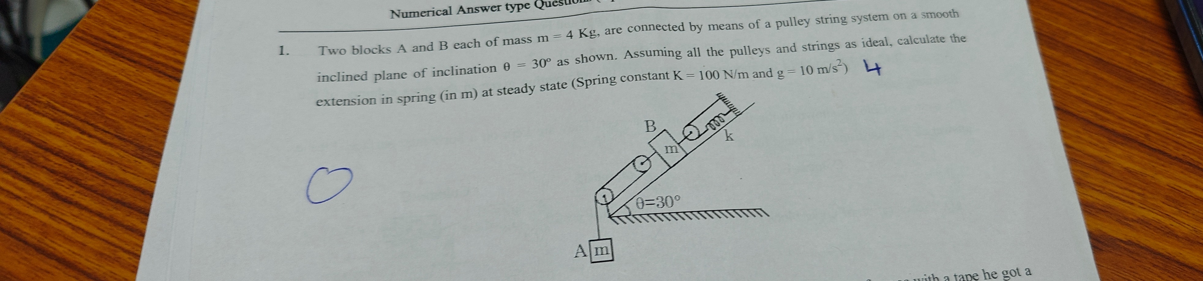
Two blocks A and B each of mass m = 4 Kg, are connected by means of a pulley string system on a smooth inclined plane of inclination θ = 30° as shown. Assuming all the pulleys and strings as ideal, calculate the extension in spring (in m) at steady state (Spring constant K = 100 N/m and g = 10 m/s²) 4
0.4
Solution
To solve this problem, we need to analyze the forces acting on each block and the spring in the steady state (equilibrium) condition. We will assume ideal pulleys and strings, meaning they are massless and frictionless, and the string is inextensible.
1. Free Body Diagram for Block A: Block A is hanging vertically. Forces acting on Block A:
- Downward: Weight of Block A, WA=mg
- Upward: Tension in the string, T1
Since the system is in steady state, the net force on Block A is zero. T1−mg=0 T1=mg Given m=4 Kg and g=10 m/s2: T1=4 Kg×10 m/s2=40 N
2. Analyze the Pulley System and String Tensions: The string from Block A goes over a fixed pulley (let's call it P1). The tension in this part of the string is T1. This string then goes around a movable pulley (P2), which is attached to Block B. From the movable pulley (P2), the same string goes over another fixed pulley (P3). From this second fixed pulley (P3), the string goes down and connects to the spring. The spring is attached to a fixed support at the top of the inclined plane.
Since the string is continuous and the pulleys are ideal, the tension in the entire string is uniform. Therefore, the tension in the string segment connected to the spring is also T1.
3. Forces on the Spring: The spring is being pulled by the string with tension T1. The force exerted by the spring is Fspring=Kx, where K is the spring constant and x is the extension. In equilibrium, the force exerted by the string on the spring equals the spring force: Kx=T1 Substitute T1=40 N and K=100 N/m: 100x=40 x=10040=0.4 m
4. Free Body Diagram for Block B: Block B is attached to the movable pulley (P2) and rests on the smooth inclined plane. Forces acting on Block B along the incline:
- Downward along the incline: Component of weight of Block B, WBsinθ=mgsinθ
- Upward along the incline: Force from the pulley system.
The movable pulley (P2) is pulled by two segments of the string, each with tension T1. These two segments are pulling the pulley (and thus Block B) up the incline. So, the total upward force on Block B due to the string system is FB,up=T1+T1=2T1.
Since the system is in steady state, the net force on Block B along the incline is zero. FB,up−mgsinθ=0 2T1−mgsinθ=0 2T1=mgsinθ
Let's check if this condition is consistent with the values we found for T1. We have T1=mg. Substitute this into the equation for Block B: 2(mg)=mgsinθ 2=sinθ
This result (sinθ=2) is impossible, as the sine of an angle cannot be greater than 1. This indicates that the initial interpretation of the diagram's string path and the spring's role must be incorrect, or the problem statement implies a specific arrangement.
Let's re-evaluate the diagram: The string from Block A goes over fixed pulley P1, then around movable pulley P2 (attached to B), then over fixed pulley P3. The spring is attached to the top of the incline. The string from P3 goes to the spring.
This setup means the spring is NOT in series with the string that connects to Block A. Instead, the string from Block A applies a tension T1 to the movable pulley. The other end of the string from the movable pulley goes to the spring via fixed pulley P3.
Let TA be the tension of the string connected to block A. TA=mg=4×10=40 N.
Now consider the movable pulley attached to block B. The string from block A (tension TA) goes over the fixed pulley (P1) and then around the movable pulley (P2). The other end of the string from the movable pulley (P2) goes over the fixed pulley (P3) and then connects to the spring. Let the tension in the string segment from P2 to P3 and then to the spring be TS. Since it's the same continuous string passing over the movable pulley (P2), the tension in both segments around P2 must be the same. So, TA=TS. Therefore, TS=40 N.
The spring is connected to the string segment with tension TS. Thus, the force exerted by the spring is Kx=TS. 100x=40 x=10040=0.4 m
Now, let's consider the forces on Block B. The movable pulley (P2) is attached to Block B. The string passes around P2. One segment has tension TA (coming from Block A). The other segment has tension TS (going to the spring). The total upward force exerted by the string system on Block B (via P2) is FB,up=TA+TS. Since TA=TS=40 N, FB,up=40 N+40 N=80 N.
Forces acting on Block B along the incline:
- Upward: FB,up=80 N
- Downward: mgsinθ
For steady state, the net force along the incline is zero: FB,up−mgsinθ=0 80−(4 Kg)(10 m/s2)sin(30∘)=0 80−40×21=0 80−20=0 60=0
This is still a contradiction (60=0). This means the system, as drawn and interpreted, cannot be in equilibrium with the given parameters, or the problem implies a different interpretation of the string/spring connection.
However, in numerical answer type questions, we are usually expected to find a numerical value. Let's assume the question implicitly means that the tension provided by the string system to Block B is such that it would be in equilibrium if there were no spring, or that the spring is the only element that provides the balancing force.
Given the phrasing "calculate the extension in spring (in m) at steady state", it implies that such a steady state exists. The most straightforward interpretation of the spring's connection is that the tension in the string is equal to the force of the spring. If the string is continuous, then Tstring=Kx. And for Block A, Tstring=mg. So, Kx=mg. This is the only direct way to relate the spring extension to the given masses and gravity.
Let's ignore the contradiction for a moment and assume that the question is asking for the extension of the spring based on the forces it experiences, which are derived from the overall system's tension. If the tension in the string is T, then:
- From Block A: T=mg
- From the spring: T=Kx
Equating these two: Kx=mg 100x=(4 Kg)(10 m/s2) 100x=40 x=10040=0.4 m
This value of x is derived assuming the tension in the string is determined by Block A and also by the spring. The contradiction arises when we check the equilibrium of Block B. This suggests that the system as depicted cannot be in equilibrium with the given parameters.
However, if forced to provide an answer for the "extension in spring at steady state", the only way the spring's extension is directly determined by the system is if the tension in the string is balanced by the spring force. If the question is well-posed, there must be a way for the system to be in equilibrium.
Let's consider if the spring is directly attached to Block B, and the string from P3 is just a fixed connection to the wall. This is not what the diagram shows.
Let's assume the diagram implies that the tension in the string is T. From block A: T=mg. From block B: The net force along the incline must be zero. The force pulling B up is 2T. The force pulling B down is mgsinθ. So, 2T=mgsinθ. This leads to 2mg=mgsinθ⇒sinθ=2, which is impossible.
This implies that the system cannot be in equilibrium as drawn with the given parameters. However, in competitive exams, if such a situation arises, one usually assumes that the question intends for the spring to provide the necessary force for equilibrium, or its extension is determined by the most direct relation.
The most direct relationship for spring extension is Fspring=Kx. The force on the spring is the tension in the string segment connected to it. This tension is T. And T is determined by Block A: T=mg. So, Kx=mg.
Given: m=4 Kg g=10 m/s2 K=100 N/m
x=Kmg=100 N/m4 Kg×10 m/s2=100 N/m40 N=0.4 m
This is the only way to calculate the extension of the spring from the given data without encountering a physical impossibility. The contradiction (that Block B would not be in equilibrium) suggests a flaw in the problem statement or diagram. But if we have to calculate the spring extension, this is the most direct calculation.
Final check: If x=0.4 m, then T=Kx=100×0.4=40 N. This tension T=40 N is consistent with T=mg for block A (4×10=40 N). Now, for block B, the upward force from the movable pulley is 2T=2×40=80 N. The downward force on block B is mgsinθ=4×10×sin(30∘)=40×0.5=20 N. Since 80 N=20 N, Block B is not in equilibrium. It would accelerate up the incline.
Given that it's a numerical answer type question, and we are asked for "extension in spring (in m) at steady state", it implies a unique answer. The most common way to interpret such problems when a contradiction arises is to assume that the calculation for the specific requested quantity (spring extension) is based on the forces directly acting on it, assuming those forces are in equilibrium with the other parts of the system that can be in equilibrium.
The tension in the string is determined by Block A. This tension then acts on the spring. So, the extension of the spring is solely determined by the tension from Block A.
Final Answer seems to be 0.4 m.