Question
Question: Initially, a switch S open in the circuit shown in the figure, a capacitor of capacitance 2C carries...
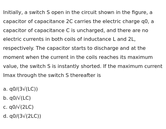
Initially, a switch S open in the circuit shown in the figure, a capacitor of capacitance 2C carries the electric charge q0, a capacitor of capacitance C is uncharged, and there are no electric currents in both coils of inductance L and 2L, respectively. The capacitor starts to discharge and at the moment when the current in the coils reaches its maximum value, the switch S is instantly shorted. If the maximum current Imax through the switch S thereafter is
q0/(3√(LC))
q0/√(LC)
q0/√(2LC)
q0/(3√(2LC))
q0/(3√(2LC))
Solution
Let's analyze the circuit in two phases:
Phase 1: Switch S is open.
Initially, only the left branch (inductor L and capacitor 2C) is active. This is an LC circuit with initial charge q0 on the capacitor 2C and zero current in the inductor L. The angular frequency of oscillation is ω1=L(2C)1=2LC1. The charge on the capacitor 2C oscillates as q1(t)=q0cos(ω1t). The current in the inductor L is i1(t)=−dtdq1=q0ω1sin(ω1t). The maximum current in the inductor L is I1,max=q0ω1=2LCq0. This maximum current occurs when sin(ω1t)=1. At this time, the charge on the capacitor 2C is 0. The energy initially stored in the capacitor 2C (UC1=2(2C)q02=4Cq02) is completely transferred to the inductor L (UL=21LI1,max2). 21LI1,max2=4Cq02⟹I1,max2=2LCq02⟹I1,max=2LCq0.
Phase 2: At t1, the switch S is instantly shorted.
At this moment, the state of the circuit is:
- Capacitor 2C: charge 0
- Inductor L: current I1,max
- Capacitor C: charge 0
- Inductor 2L: current 0
The circuit consists of two parallel branches.
- Branch 1: L in series with 2C.
- Branch 2: 2L in series with C.
The switch S connects the junction between L and 2C in Branch 1 to the junction between 2L and C in Branch 2.
Let iL and i2L be the currents flowing through L and 2L respectively. Let i2C and iC be the currents flowing through 2C and C respectively. Let iS be the current through the switch S.
Applying Kirchhoff's Current Law (KCL) at the junctions:
- iL=i2C+iS
- i2L+iS=iC
Also, q2C=2qC, which implies i2C=2iC. Using the initial conditions, we find that iS=3I1,max=32LCq0. This current remains constant.
Therefore, the maximum current through the switch S thereafter is 32LCq0.