Question
Question: In the network shown, the potential difference between A and B is: (\(R = {r_1} = {r_2} = {r_3} =...
In the network shown, the potential difference between A and B is:
(R=r1=r2=r3=1Ω,E1=3V,E2=2V,E3=1V)
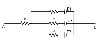
(A) 1V
(B) 2V
(C) 3V
(D) 4V
Solution
Hint
Resistance R is not connected to a closed circuit. The resistors r1, r2 and r3 are configured in parallel. Thus, current flowing through one of them doesn’t have to flow through the others.
Formula used: V=IR where V is the potential difference across the points considered, I is current, and R is resistance.
Req1=r11+r21+r31 where Req is the equivalent resistance of the parallel resistors r1, r2 and r3.
Complete step by step answer
The resistors r1, r2 and r3 are in parallel configuration. Thus, Ohm’s law can be applied to each of the resistors. This is because parallel resistors loop back on themselves without its current passing through the other resistors. No current flows through resistor R since it’s not part of a complete loop, thus an open circuit.
An alternate way to draw the circuit above is shown below.
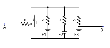
From the diagram above, it is clear that current can pass through the resistor r1 without passing through r2 and r3.
Similarly for the resistorr2 and r3.
For current passing through r1 we can use ohm’s law, i.e.
E1=I1r1
⇒I1=r1E1
Substituting the values in the question, we have
I1=13=3A
Similarly for r2,
⇒I2=12=2A
And finally for r3,
I3=11=1A
Now, let us find the total current flowing in the circuit. This is given as
I=I1+I2+I3
Substituting each values into the formula, we have
I=3+2+1=6A
Next, let’s calculate the equivalent resistance of the parallel connections. This is given as
Req1=r11+r21+r31
Substituting their respective values
Req1=11+11+11=1+1+1
⇒Req1=3
By inverting both sides we get,
Req=31Ω
Finally, the potential difference between A and B is
PD=IReq
Therefore, by substituting
PD=6×31
∴PD=2V
Hence, the correct option is B.
Note
A point of confusion is why no current flows through resistance R despite being part of the circuit. To understand this more clearly, observe that the point AB is open, i.e. the current doesn’t flow from A to B. It can be considered as a stray wire (which may be connected to a voltmeter or similar devices). Thus all current flow within the parallel configuration, and that is all is needed to be analyzed.