Question
Question: In the given figure, the potential difference is shown on \[R\], \[L\] and \[C\]. The emf of source ...
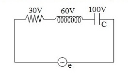
In the given figure, the potential difference is shown on R, L and C. The emf of source in volt is
A) 190
B) 70
C) 50
D)40
Solution
In this question, the given circuit is RLC and AC source is applied, so the concept of the resultant voltage concept will be used that is induction voltage and the capacitance voltage are at same phase while the resistance voltage are at perpendicular phase.
Complete step by step answer:
A standard RLC circuit consists of a resistor, an inductor and a capacitor in series. We consider the voltage across the resistor VR, the voltage across the inductor VL, and the voltage across the capacitor to be Vc.
Now this type of circuit has a specific frequency at which it resonates. That is called the resonating frequency.
So, the standard formula to be used in simple series RLC circuit is-
⇒Ve=VR2+(VL−VC)2
From the given circuit, we have VR is 30V, VL is 60V, and VC is 100V. Now, we substitute the given values in the above equation as,
⇒Ve=302+(60−100)2
Now, we simplify the above equation as,
⇒Ve=302+(−40)2
After calculation we get the result as,
∴V=50V
Hence, the voltage from the emf source obtained across the series combination of the given RLC circuit is 50V.
Thus, the correct option is C.
Note: We have seen that the three basic components in a circuit are Resistance, Inductance, and Capacitance have very different phase relationships to each other when connected to a sinusoidal alternating supply which in this case is the source of the emf given. The negative sign in the formula of the net voltage indicates that the inductor is ahead of the capacitance by some degrees phase angle. If the circuit is completely a resistor circuit then the difference in voltages of the other two would have been zero. The resistance of an inductor is Lω, and that of capacitor is Cω1, where C is the capacitance and L is the inductance provided.