Question
Question: In the given circuit, the AC source has \(\omega = 100rad - {\operatorname{s} ^{ - 1}}\). Considerin...
In the given circuit, the AC source has ω=100rad−s−1. Considering the inductor and capacitor to be ideal, the correct choice(s) is(are):
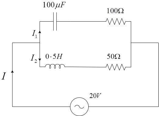
A) The current through the circuit, I is 0.3A B) The current through the circuit, I is 0⋅32A C) The voltage across 100Ω resistor = 102V D) The voltage across 50Ω resistor = 10 V
Solution
If there was a DC source, we could have directly considered the parallel combination of resistors and calculated the net current from the total resistance. As there is an AC source, along with the resistances, we have to also, account for the reactances offered by the inductor and the capacitor, while calculating the branch currents across the branches. Also, we cannot directly add the impedances as we do in parallel circuits, since the values will be in different phases. So, we have to draw a phasor diagram to solve for the net impedance and hence, the net current in the circuit.
Complete step by step solution:
We have to calculate the individual currents in the branches.
The impedance is the obstruction offered to the flow of A.C current in the circuit.
To find the net impedance in the circuit, we have to individually calculate the impedance of the top branch and then, the individual currents and then, we can add the phasors.
Impedance in the lower branch, Z1=XL2+R12
Z1=(ωL)2+R12
Given the angular frequency, ω=100rad−s−1
Inductance, L=0⋅5H
Resistance in the lower branch, R1=50Ω
Substituting, we get –
Z1=(ωL)2+R12
Z1=(100×0⋅5)2+502
⇒Z1=502+502
⇒Z1=502×2
⇒Z1=502Ω
The direction, θ1=tan−1(RXL)=tan−1(5050)=45∘
Current through the lower branch, I1=Z1V=50220
Similarly,
Impedance in the upper branch, Z2=XC2+R22
Z2=(ωC1)2+R22
Given the angular frequency, ω=100rad−s−1
Capacitance, C=100μF
Resistance in the upper branch, R2=100Ω
Substituting, we get –
Z2=(ωC1)2+R22
Z2=(100×100×10−61)2+1002
⇒Z2=(104×10−61)2+1002
⇒Z2=(10−21)2+1002
⇒Z2=1002+1002
⇒Z2=1002Ω
The direction, θ2=tan−1(RXC)=tan−1(100100)=45∘
Current through the upper branch, I2=Z2V=100220
Therefore, the current in the upper branch is I2=100220A at 45∘ and the impedance in the lower branch is I1=50220A at 45∘. Plotting them on the phasor diagram, we get –
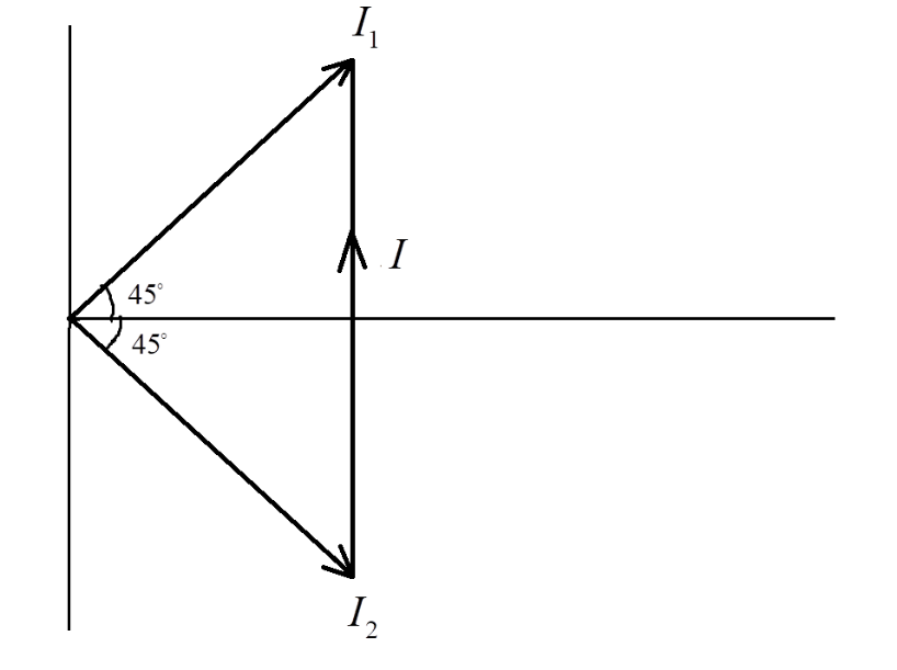
From the phasor, the net current I, is the vector sum of the individual currents. From the above figure, we get –
Magnitude of I,
I=I12+I22
Thus, I=(0⋅28)2+(0⋅141)2=0⋅098=0⋅313A∼0⋅3A
The net current in the circuit, I=0⋅3A
Voltage across the 100Ω resistor is given by, V=I1R=50220×50=220=210×2=102V
Voltage across the 50Ω resistor is given by, V=I2R=100220×50=210=7⋅07V
Thus, Statement-A and Statement-C are the only correct statements in the above question.
The correct options are Option A and Option C.
Note: While solving the problem, the students should always note the direction of the current and the relationship between the voltage and current in the phasor diagram.
Note that the current I1 is in the top and current I2 is in the bottom because in a capacitor, the current always leads the voltage and in an inductor, the current lags the voltage. The students must remember this, while drawing the phasors.